This thread has been locked.

If you have a related question, please click the "Ask a related question" button in the top right corner. The newly created question will be automatically linked to this question.

TPS65987D: TPS65987D no output power to device, IOs restarting

Part Number: TPS65987D
Other Parts Discussed in Thread: TIDA-050012

Hi,

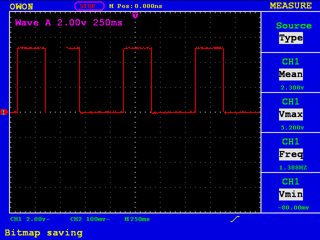
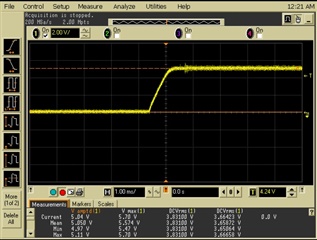
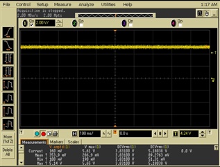
My team has a charger design based on the TPS65987D. It looks quite familiar to the TIDA-050012 EVM board where GPIOs are controlling the output voltage of the DCDC. If a GPIO is enabled the enable on the DCDC is also pulled high. When inserting a phone (tested with two different devices) for charging, the correct voltage is selected (5V in this case), and the DCDC starts to output 5V. No voltage are on VBUS1/2. However after ~250ms the TPS65987D releases the GPIO and restarts. This makes the DCDC to restart its output. From the logs it seems as the board reports overvoltage on the VBUS (VBUSState_MON_HI (0x90))? But when measuring the voltage it is maximum 5.2V. Why do we get this behavior?

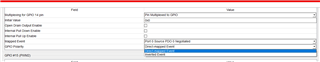
Attaching project file, log file and measurement of output from DCDC.

Best regards,

Simon

  Debug_log.csvTestSoftware_noPowerPath_new.pjt

  • Hello,

    Would you be willing to share some more information regarding the schematic?  Also in the screen shot above can you provide more resolution (overshoot/undershoot) of when the DCDC is enabled?

    Thanks and Regards,

    Chris

  • Hi,

    Thank you for the feedback! I can share the schematics in PM. I cannot see any overshoot of the voltage. Vmax amplitude seems to be max 5.11V. It seems to be a timing related issue. I have now force enabled the DCDC and set it to 5V. The 5V charging then works as expected (Vmax amplitude at 5.14V). If I keep the 5V only but enable the DCDC from GPIOs I get the same behavior as before.

    Zoomed in oscilloscope pic of output from DCDC:

    Forced only 5V output from DCDC:

    Best regards,

    Simon

  • Hi Simon, 

    TI US is currently on holiday and will return July 5th, thank you for your patience!

    Thanks and Regards,

    Raymond Lin

  • Simon,

    Thank you for the additional information.  I will review and provide a response on 07/06/2023.  Is there a specific reason you use GPIO to enable the DCDC instead of automatically enabling?

    Regards,
    Chris

  • Yes and no. As you can see in the schematic, setting both VSEL1 and VSEL2 to both 0 yields the voltage 20V. Then the TPS65987D turns off (same behavior as with late enable), which is kind of expected. However I have tried setting the initial value in the application to 0x1 (also tried decimal 1) instead, which would probably fix this issue. But I cannot get this to work, the GPIOs always starts at 0V.

  • Hello Simon,

    I do not have a good answer at this time.  You need to establish the 5V implicit contract before moving to the 5V explicit contract or other contract.  To confirm I was thinking you could simply take GPIO14 and set it high to always select 5V.  This would be just to confirm the phone test you are trying with 5V contract.


    Chris

  • Hi Chris,

    Setting the GPIO14 as in your picture (changing the "Mapped Event") seems to work. The GPIO is high at boot and I can charge the phone at 5V (VSEL2 is at the moment pulled high externally). However when I change back to "Port 0 Source PDO 0 Negotiated" it's initial value is 0 again (I have not changed the "initial value setting"). I can see that the DCDC starts lowering the voltage to 5V, but the controller releases the GPIO before it's any lower than ~6V.

    Best regards,

    Simon

  • Simon,

    Thank you for checking that.  I am trying to figure out how to reuse your logic and inverting the GPIO polarity in the configuration.  Let me know if you have any flexibility on your board.

    Regards,

    Chris

  • Hello,

     Based upon your previous response, it appears that the issue is the transition between EN=VSEL1=VSEL2=0 (20V disabled) and EN=1,VSEL1=VSEL2=0 (5V Enabled).  By 'fixing' GPIO14 as a logic '1' output the regulator starts at 5V before the explicit contract is negotiated.

    You would need to change your logic so that the 5V is always enabled by default and then once a different contract is negotiated then higher voltages are provided.  Please consider changing your logic.  Additionally you can also invert the logic in the GUI:


    Regards,
    Chris