This thread has been locked.

If you have a related question, please click the "Ask a related question" button in the top right corner. The newly created question will be automatically linked to this question.

TPS61196: Regulator Startup Issue/Sanity Check

Part Number: TPS61196

Thank you for your time today.

We're looking to use TPS61196 in an application, and I'm having an issue getting the regulator to startup.  To note, on both chips VDD hits ~6V when (simultaneously) enabled and PWM1-6 appear to function, albeit with VOUT at VIN instead of boosting.

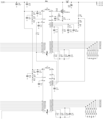
While still investigating, I'd appreciate a sanity check on my values to ensure I'm not out in left field looking at the sky.  Below are the relevant portions of the schematic and a page whipped up for calculation.

Some quick questions (re: datasheet, relevant excerpts in link):

  • I believe I'm misinterpreting the equation in figure 1, as it looks to contradict Table 1/Figure 4.  For 400kHz switching, I definitely should be using 100k Ohms, not 100 Ohms?
  • For the "Multi-Chip Operation In Parallel" diagram in figure 22, some components from the single chip layout are omitted (C8, R13-18).  Is this intentional or is the drawing meant to only illustrate the connections with the heavier weighted red lines?
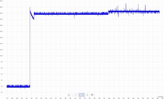
  • Assuming the presence of R13-18, if C8 was omitted, could the (admittedly possibly unstable?) startup exhibit the behavior shown in the graph below?  Apologies for lack of ISNS data, will check today.
  • Generally, does anything else in the schematic or linked page stand out as incorrect?

Thank you again,

Elliot Kampa

Calculations:  https://dev.ilot.net/TahPei3ahP/tps61196_demo1/tps61196.html

Schematic excerpt:
Startup issue capture, Vout @ L1:
  • Hi Elliot,

    I will reply to your questions later, thanks for your patience.

    BR

    Patrick

  • Thank you Patrick.

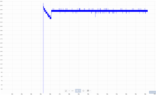
    To add to the data, yesterday I tried a single chip configuration using only one channel (others terminated with 20k per datasheet).  There now is a driving waveform at the base of the Q1.  The enable pin was connected at ~15s and the PWM pin for the channel at ~28s.

    Please disregard my third question - the startup "stepping" looks the same in this state.

    After thinking about it more, I believe I may have damaged the TPS61196 with my original configuration.  The LED I am using to create the strings has one(1) 2.0V channel and three(3) 3.2V channels (RGBW, respectively).  I had added series resistance to compensate at 100mA, but failed to account for the change to the characteristic curve of the channels during any ramp up.  As we plan on using four(4) of these chips per board, I will try driving all 2.0V channels on their own chip, completely independently, if required.

    Update, 2 days later: Never mind about the ramp up.  Made another batch of untouched boards, had the same red channel issue running one channel independently.  Checked each board and the red channel was shorted on some of the LEDs.  Looked at the datasheet again, the datasheet's recommended footprint doesn't line up with the product.  Checked the manufacturer's site, there's a newer version of the datasheet with an updated footprint.  Moral: manufacturers suck at updating vendors when they rev datasheets.  Still testing the difference in the chains on the shared regulator, still putting red on a separate, 2nd chip in a pair.

    The average voltage for the single chip configuration still averages ~24.5V once the PWM is enabled, however this is with the component values calculated for the dual configuration.

    More update: Double checked the amperage drawn by the chain - it's correct at 100mA, leading me to believe there is a wide variance between parts.

    I'll test proper component values for the single chip configuration, the dual chip configuration without the 2.0V channel, and with the 2.0V channel isolated  Monday and report back.

    Thank you again for your time and any insight.

    Yet more update: I've reached the conclusion that the first chips blew up due to the shorting on the footprint and that the TPS61196 is working flawlessly.  Would still appreciate answers to the outstanding questions and confirmation of the calculations.

  • Hi Elliot,

    Due to some conflicts, I will reply to you tomorrow.

    BR

    Patrick

  • Hi Elliot,

    Could you please summarize the test setup? Including the Vin, Vout, LED current and what is the connection of the IFB pins.

    BR

    Patrick

  • Vin = 24V

    Vout = 25.6V

    LED current = 100mA

    IFB pins are connected to the cathodes of the last LEDs in the strings.

  • Hi Elliot,

    For the dual chip configuration (which we called master-slave mode), could you please measure the REF voltage waveform of U6 (the upper IC in your schematic) when you powering on the system. Let's see if this voltage is ramping up normally or not.

    BR

    Patrick