Hi, TI expert.
The recommended output inductor is 220 to 350nH, but what happens if you use an inductor other than this recommended value? For example, what kind of behavior would you expect if you put in a 110nH inductor?
Best regards
This thread has been locked.
If you have a related question, please click the "Ask a related question" button in the top right corner. The newly created question will be automatically linked to this question.
Hi, TI expert.
The recommended output inductor is 220 to 350nH, but what happens if you use an inductor other than this recommended value? For example, what kind of behavior would you expect if you put in a 110nH inductor?
Best regards
Hello Gomi,
The obvious direct spec that will be affected by the inductor is the inductor current ripple (delta IL) and eventually will affect the VOUT ripple and the current limit that is based on inductor current detection on the LSFET of this device. COUT has to be adjusted accordingly due to changes in inductor current ripple and output voltage ripple. The Peak current and the RMS current are also will be directly affected as explained in the datasheet. Going too low in inductor will start affecting the transient response of the device and eventually the stability during normal operation.
Follow equation 5 thru 8 in the datasheet to design the appropriate L and C combination based on your needs and given spec for your application such as Maximum input voltage, Output voltage, and selected Switching frequency. Once you get the inductance value, you need to select the DCR, Itemp and ISAT of the inductor in such away that it will handle the current/Load, efficiency and thermal requirement of your application.
Hope that helps
Thanks!
Tahar
Hello Tahar,
"Going too low in inductor will start affecting the transient response of the device and eventually the stability during normal operation. "
In 4MHz drive mode, SWA and SWB are alternately driven at 2MHz.
Will this synchronization not work properly?
Or will the 2MHz drive not work properly in the first place?
Or am I looking at the wrong point?
I am very sorry to bother you while you are busy, but I would appreciate your kind cooperation.
best regards.
Gomi Ryota,
What is your goal with using an inductor value outside the recommended values?
If sync'ing to external clock, the external clock of 4MHz +/-10% should be connected to SYNC pin.
The power stages will switch at 2MHz each (1/2 of internal oscillator or sync pin signal frequency of 4MHz).
The inductor value is calculated based on the switching frequency.
Typical design practice is to choose an inductance such that the inductor ripple current is 10% to 40% of the output current.
If using a 110nH, the ripple current is high about 80% of Iout and Tahar discusses many drawbacks.
An additional drawback is when the load current is less than the ripple current, the efficiency will be lower.
David Daniels,
There is an inductor with a very small radiated magnetic field, but with a constant of only 110nH.
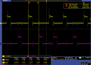
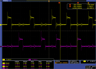
When I actually put this inductor on and move it, there is no problem with the output voltage and current, but only the drive frequency behaves strangely.
I want to know why. The attached diagram shows 4MHz drive mode because both SS/FSEL and SYNC are open.
I also have a question associated with frequency.
This DCDC is PWM controlled, but the single-phase frequency fluctuates between 1980 and 2000MHz.
Will the drive frequency fluctuate if the clock is not input to SYNC? If so, please tell me the factors behind the variation.
Best regards.


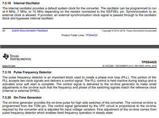
The TPS54A20 uses on time control for fast transient response and a phase lock loop (PLL) to achieve a fixed frequency control during steady state.
The PLL adjusts the on time to achieve fixed frequency.
I believe the output voltage drooping causes the device to switch the high side fet. The smaller inductor value will have larger output ripple.

I understand that it drives only ONtime according to the clock called PLL control.
So, when I actually measured the radiated magnetic field, it radiated a magnetic field of 1940 to 2000 kHz, so I don't think it is stably driven at 2 MHz. Why is that?
Also, as in the image attached before, when the 110nH inductor is actually placed, the LX waveform behaves strangely. Why is that?
The ringing on the sw nodes is from using a scope probe with long ground leads Use the tip and barrel measurement technique or a differential probes to measure SW and minimize ringing.
To have good load transient response, when the output voltage (FB pin voltage) falls below internal reference voltage, the high side fet turns on for the ONtime. The ontime is adjusted with the PLL to have a steady state switching frequency.
In the scope plot, the CH3 turns on as the CH1 turns off. The CH1 turn off is probably causing an output voltage ripple to trigger CH3 SW.
If the output voltage is plotted with sw nodes, I believe you will see the FB pin is dropping below the internal regulator.
Have you tried increasing the Cout or increasing the inductance to resolve the issue.