This thread has been locked.

If you have a related question, please click the "Ask a related question" button in the top right corner. The newly created question will be automatically linked to this question.

LM5116: Current limiter kicks in prematurely

Part Number: LM5116
Other Parts Discussed in Thread: TPS40057, TPS40170, LM5148

Hi,

I very recently got some excellent help from guru EricLee, so now my buck converter runs quite smoothly. Until I add some load above 4 A, that is. I've gone through ≈ 15 pages of LM5116 related threads, but haven't found anything I believe matches my situation. Sadly.

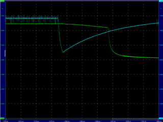
My problem is that somewhere between 4 and 5 A load, the buck converter starts engaging the hiccup current limiter. I am quite sure it is the current limiter, because UVLO is briefly pulled low, and the timing checks out (slightly over 1,3 ms @ 195 kHz fSW).

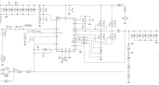
Partial schematic, greatly inspired by WEBENCH:

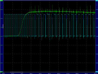
Load current and SW (blue). The spikes on the load current (green) are only visible when I connect the 2nd probe to SW. The scope is trigged by the load, so the current limit countdown starts shortly after the load is applied.

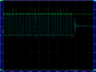
Load current and UVLO (blue):

The current sense resistor is 3 mΩ, and is Kelvin connected. I have added a 1 nF capacitor between CS and CSG – that didn't seem to change anything. The 48 V supply is rock solid, and doesn't limit the current at this quite low power consumption.

Any ideas about what is happening here?

Should I perhaps replace R50 and R51 with som smallish resistors, such as 47 Ω, to improve filtering?

Could it be shoot-through in the high and low side FETs? Should I add a few Ω in series with HO, and possibly also LO, to reduce possible ringing?

Any assistance will be greatly appreciated.

Br, Erik

  • Hello Erik 

    Please download Quick Start https://www.ti.com/lit/zip/snvu051 , input your component selections and find the required Cramp and Rramp values. . 

    Assuming 30VOUT, you need 1~nF Cramp in addition with ~150kohm Rramp. 

    The current limit level will be decreased by reducing the Cramp or Rramp more than required. Please refer the Figure 29 in the datasheet. 

    -EL 

  • Hi Eric,

    Yes, I wondered about that, but dismissed it due to the approximations in section 7.3.7 in the datasheet, where CRAMP is omitted from the equation. The original 1.2 nF capacitor made the converter unstable, but it is quite possible that the 150 kΩ resistor can change that.

    Will try it tomorrow. Too tired now.

    Br, Erik

  • Hello Erik 

    Please let me know if any update.  

    -EL

  • Or course. Whatever happens, I'll let you know.

    Br, Erik

  • Hello Erik 

    You don't need to reply if no update. 

    -EL

  • Hi Eric,

    I used the quickstart spreadsheet, changed CRAMP back to 1.2 nF, and added an RRAMP = 120 kΩ. Sadly, it made things worse.

    Now the controller enters that unstable regime when the load current reaches about 5 A, and eventually shuts down after about 1.6 ms.

    Green trace = load current (A). Blue trace = SW.

    I am beginning to think that this buck controller isn't suitable for what I am trying to do. In my design, the buck converter feeds a linear current regulator, that generates relatively short current pulses. In order to minimize the power loss in the current regulator, and to accommodate different loads, the buck converter output voltage is adjustable. I've done this several times before with the older TPS40057 and the TPS40170. However, as the supply voltage is 48 V, TPS40057 and its successor are out of the question, and the maximum input voltage of the TPS40170 is too close for comfort. So that's why I chose the LM5116.

    This is the first time I'm using a current mode control buck converter, and I have been taken aback by its complexity.

    If there is a glimmer of hope in the distance, please let me know.

    Best regards,

    Erik

  • I am considering going back to the 330 pF CRAMP that I had before, and adding a 1:4 voltage divider to CS / CSG. But better suggestions are appreciated.

  • Hello Erik 

    If you have to adjust VOUT dynamically, please consider LM5148 peak-current-mode buck controller (if it is not too late). Unlike LM5116, LM5148  device doesn't require Cramp/ Ramp change by changing VOUT dynamically. Also, LM5116 employees an emulated-current-mode not the peak-current-mode. 

    -EL  

  • Hi Eric,

    Thanks a lot. This helps me more than you imagine.

    Luckily, this board is somewhere between being a prototype and proof of concept. So there will be (at least) a second spin.

    The immediate need from my customer is probably a quite narrow voltage range. So my thought is that if I can just make the buck controller work in that range, then the customer can actually work with the existing boards. In the next spin, I will replace the LM5116 with something more suitable.

    I have looked at the datasheet for the LM5148, and agree that this would be a much better choice in my application.

    Thank you for all your help, Eric. Much appreciated!

  • Thanks for choosing TI. Please feel free to contact us if you have any question.
    -EL