


I am using TI part TPS22953DQCR.
The EN pin is supposed to have <0.1uA of leakage current.
I thought that meant I could safely use a 357k (high side) and 100k (low side) resistor divider network on the EN pin.
I learned that those values don't work well and cause the load switch to turn off frequently.
I don't have good guidance from the datasheet for the max resistor values I can safely use.
We did further testing and the EN pin leakage current appears to be ~1 to 3uA with Vbias of ~3.2V.
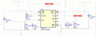
Below is our circuit. The BATTERY_RAW net is supplied by a single cell li-ion battery pack.
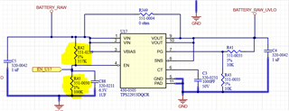
R41 is depopulated. R349 is depopulated. We have the issue with or without C88 populated.
We have an additional ~200uF load capacitance on the output.
We can get the load switch to work correctly if we change R42 to 35.7k and change R45 to 10k (10x lower than the original values). This fixes the load switch behavior, but results in higher than desired quiescent current draw from the li-ion battery pack. Again, it is unclear why the original resistor values wouldn't work based on the specs in the datasheet.
