This thread has been locked.

If you have a related question, please click the "Ask a related question" button in the top right corner. The newly created question will be automatically linked to this question.

TPS55340: Schematic Review

Part Number: TPS55340

Hi,

Can you please kindly review my below schematic i am using part TPS55340RTE, 

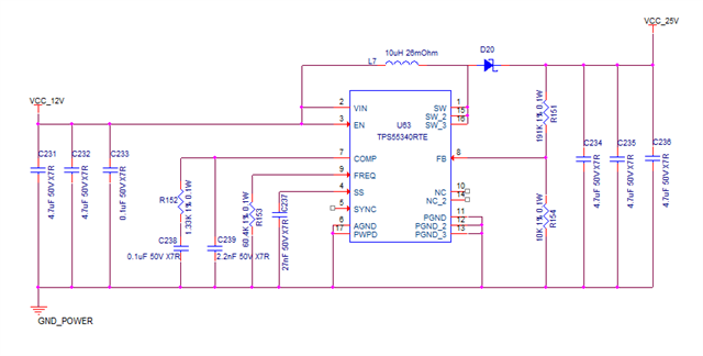
I have taken this from reference design, my aim is to only boost up the voltage to 24V to bias a photo diode, should i need to any extra capts to serve the purpose ?

  • Hi Shyam,

    Thanks for your interest in the TPS55340 device.
    The design structure looks good to me.

    To validate your inductor and compensation values, I recommend using our quickstart calculator tool for TPS55340:
    https://www.ti.com/tool/download/SLVC430
    This tool will also give recommendations considering the max load conditions, which I cannot see right now just from the schematic.

    General tips on output capacitance is to use both ceramic caps (for filtering the switch current ripple) and electrolytic bulk caps (for compensating strong load transients).
    Also always check the DC bias derating values of the ceramic caps, as the actual capacitance may be lower at 25V than at 0V.

    Best regards,
    Niklas