This thread has been locked.

If you have a related question, please click the "Ask a related question" button in the top right corner. The newly created question will be automatically linked to this question.

LMR51440: Ripple frequency in LMR51440SDRRR

Part Number: LMR51440

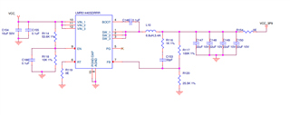
We are using the LMR51440SDRRR for the purpose of converting 24V to 3.9V.

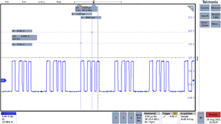
As per our understanding if we use a 0 Ohm resistor between RT pin and ground, the output the frequency of the regulator should be 1MHz, but under our observation it near 500KHz for current above 500mA(approximately). Why does the frequency is not matching the set frequency.

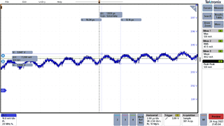
Another observation is that when the load increased beyond 500mA the voltage waveform seems to have a lower frequency component (near 10KHz) along with the ripple frequency, why does this lower frequency component occur in the output?

  • Hi,

    1. Can you increase the load to see if operates with 1MHz? It's probably working under PFM as the load is light. 

    2. It's probably the frequency under PFM. 

    Can you share the waveforms for both questions?

    Regards,

    Hongjia

  • Hi,

    1.We tried increasing the load and the frequency reaches near 1MHz when the load current increased up to 1A, Do the IC have any current limit above which it works in PWM mode?

    2.The output waveform has a lower frequency component superimposed on the ripple frequency. Please refer the attached image, The ripple frequency is around 500KHz and the total ripple waveform changes by 8KHz.

    Thanks,

    Saran S

  • Hi Saran,

    1. When either the minimum high-side switch ON time tON_MIN or the minimum peak inductor current IPEAK_MIN (0.8-A typical for LMR51440) is reached, the switching frequency decreases to maintain regulation.

    2. The low frequency ripple is because of the spread spectrum function. LMR51440 integrates triangular spread spectrum which can benefit EMI but you will see the low frequency ripple on the output.

    Regards,

    Hongjia

  • Hi,

    Thanks for your answers, we had captured waveform in the switching node of the regulator, you can see the waveform have an inactive time period region where the pulse is off and then a PWM signal for a particular time period. Can you confirm whether this is due to the spread spectrum feature in the regulator?

    Thanks,

    Saran S

  • Hi,

    Can you share your schematic and test condition for the image you captured above?

    Regards,

    Hongjia

  • Hi,

    Please find the attached image for the schematic,

    Test Condition,

    Input voltage :12V

    Output Voltage:3.9V

    Output Current:1A

    We tested it with a variable resistive load.

  • For 1MHz frequency, 6.8uH inductor is too large. Change a small inductor like 2.2uH and see if the SW node is stable.

  • Hi,

    We calculated the inductor value for 30% current ripple.

    How is this inductor value related to the switching characteristics of this regulator?

    Thanks

  • Hi Saran,

    As the internal compensation is designed based on 4A output, usually we choose the inductor based on the 4A output for LMR51440. Did you change the inductor and see any improvement? Another thing we can do is removing Cff because this capacitor is also loop related. 

    Regards,

    Hongjia

  • Hi Saran,

    As there is no response for quite a few days, I will close the thread. Let me know if you have further questions.

    Regards,

    Hongjia