


Hi expert
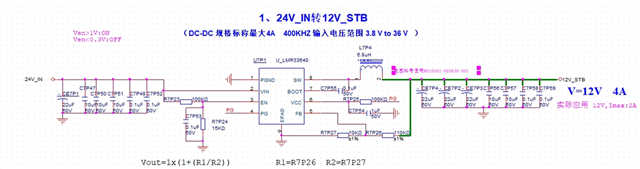
could you please help review the schematic of LMR33640, it's used on the STB, the actually output is 12V 2A
the inductor parameter: I sat =10A,I_TEMP=6A, DCR=44mohm.
Hi expert
could you please help review the schematic of LMR33640, it's used on the STB, the actually output is 12V 2A
the inductor parameter: I sat =10A,I_TEMP=6A, DCR=44mohm.
