


When looking for a power supply for an AC/DC system, high efficiency, high power factor (PF) and low power line harmonics are all of major concern. This article will take a look at power factor correction (PFC), its uses, different topologies, and how totem pole PFCs can be useful for power supplies.
What is Power Factor Correction (PFC)?
To understand PFC, we must first define what power factor (PF) is and how PFCs solve it. PF can be simply stated as the ratio of real power (W) divided by the apparent power (VA). The real power is what is consumed by the load and the apparent power is what is circulating between the source and the load. The ideal power factor is 1, meaning that there are no losses due to reactive power (VAR) and all apparent power is real power (VA = W). In most cases, a power factor of above 0.85 is acceptable depending upon the system and its needs. In AC systems, the phase shift between the current and voltage waveforms correlates to the PF. This value of PF can be found by calculating the cosine of the phase shift angle between the voltage and current. The waveforms of a system with a PF of 1 and of 0.4 can be seen in Figure 1 below. Note the increase in current due to the decreased PF.
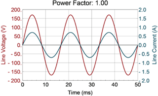
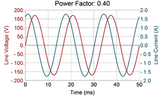
Figure 1 Voltage and current waveforms depicting a PF of 1 and a PF of 0.4.
Total harmonic distortion (THD) is another common point of concern when discussing power quality and power supply efficiency. THD is the sum of all of the harmonic components of a signal, particularly current, and that sum is compared to the fundamental frequency. THD is created by all of the frequencies in a signal that are harmonics of the fundamental frequency. With more harmonics, the sine wave of the signal begins to look less and less like a sinusoid, which has undesirable effects on the electrical system. These include increased current, increased core losses in motors, and Electro-Magnetic Interference (EMI) with other electronic equipment.
Both PF and THD can be mitigated through Power Factor Correction (PFC), which can be approached either actively or passively. PFCs are able to provide low THD and high PF by utilizing the energy storage characteristics of the inductors and capacitors. An example of a typical passive PFC circuit can be seen below in Figure 2.
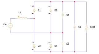
Figure 2 Simple Passive PFC Circuit Diagram with a Diode Rectifying Bridge
For a more in-depth explanation of power factor correction, reference the “Power Factor Correction (PFC) Circuit Basics” document.
What are the typical PFC topologies?
PFC topologies are characterized as being either active or passive. In the passive approach, passive components such as inductors and capacitors are added to the circuit with the diode bridge. In the active PFC approach, a full power converter stage is utilized instead of the inductor or capacitor banks and offers greater performance as they are effective over a wide variety of operating ranges. One of the simplest options for PFC is using a passive PFC with passive components such as capacitors and inductors in order to filter the output signal of the rectifier and improve power factor. Passive PFC is typically useful for small (<100W) systems that have linear loads and remain in a steady-state. The current from the AC source is still in bursts that are due to the charging and discharging of the output filter capacitor and the passive approach cannot accommodate that change effectively. This is a limited approach and is not effective for a wide variety of operating ranges due to no variability or adjustability once constructed. A passive PFC example is shown below in Figure 3.
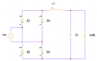
Figure 3 Passive PFC circuit with diode bridge rectification.
The alternative to passive PFC is active PFC which involves switching. One example of an active PFC is a boost PFC. A boost PFC is a simple approach which utilizes an inductor, a switch (MOSFET) and a diode to create a boost converter on the secondary side of the rectifying bridge. To drive this MOSFET, a single channel, low-side gate driver like the UCC27517A can be used. This approach is typically used between power levels of 100W and 4kW. The boost converter rapidly switches with varying duty cycle of around 20-40kHz to make the input current sinusoidal and in phase with the input voltage, correcting the PF phase shift and improving the power factor. These MOSFETs are driven at these high frequencies with gate drivers that provide high speed and high current output for maximum efficiency. The boost converter PFC topology can be seen below in Figure 4.
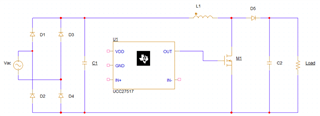
Figure 4 Boost PFC using a MOSFET, rectifier bridge, an inductor and a diode with an output capacitor filter.
A step up from the boost PFC is the interleaved boost PFC. The interleaved boost PFC offers additional improvements to system efficiency but at the cost of additional components. The interleaved boost converter PFC uses a rectifying diode bridge and two boost converters in parallel that are phase shifted (interleaved) to improve efficiency and reduce input current ripple. To drive these two MOSFETs, a dual channel, low-side gate driver like the UCC27624 can be used. This topology can be seen below in Figure 5.
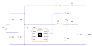
Figure 5 Interleaved Boost Converter PFC with parallel boost converters and a diode rectifier bridge.
Another popular PFC topology to consider and that is an active, bridgeless topology. The totem pole PFC topology is an active, bridgeless topology that replaces the diode rectifying bridge with additional switches (MOSFETs). Switching from a diode bridge to SiC MOSFETs allows for only two junctions to be in series as opposed to three in the boost converted topology shown previously. This allows for faster switching in the range of 100-250kHz and lower reverse recovery charge which leads to reduced switching losses in the system. At these frequencies, a suitable, dual channel gate driver is needed in order to output the high current needed for the power MOSFETs to maintain maximum efficiency. Below, you can see two configurations for the Totem Pole PFC topology in Figure 6 and Figure 7.
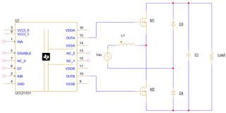
Figure 6 Totem Pole PFC circuit utilizing diodes for line rectification.
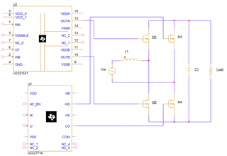
Figure 7 Totem Pole PFC circuit utilizing MOSFETs for line rectification.
For the totem pole topology, there are two branches of switching used, the right-side branch shown above with either two silicon MOSFETs or two diodes and the left branch with two SiC MOSFETs (or GaN FETs). The right-side branch is called the slow leg and is used for line rectification of the AC signal that is at grid frequency which is typically 50/60Hz. This slow leg can be driven by a UCC27714 as these FETs are very high powered and need the high current supplied by this driver. The left side branch is the fast leg that is used for stepping up the voltage and shaping the input current. This fast leg switches at high frequencies such as 100-250kHz and can be driven by the UCC21551.
What is Totem Pole PFC used for and how is it advantageous?
AC-DC power supplies, such as those used in servers, networking, telecommunications, industrial systems, and electric vehicles, are all critical systems when it comes to the need for high PF and high efficiency. When looking at the boost style PFCs in comparison to the totem pole PFCs, the DC-DC stage of the boost topology can account for a much as 2% of loss and the line rectification can account for another 2%. This can be a problem when considering the extreme standards set forth in the power supply industry but groups such as EnergyStar and the IEM 61000-3-2. The interleaved boost converter contains 8 total switching components such as MOSFETs and diodes whereas the totem pole PFC topology only utilizes 4 switching components. This allows for less conduction losses due to fewer components. When comparing the efficiencies of different topologies, the standard Boost PFC can reach peak efficiencies of up to 95-97% and the interleaved boost PFC can improve upon that with efficiencies of 97-98%. But with the totem pole PFC can reach efficiencies of 98-99.5%. These increased efficiencies across these three topologies comes at higher cost as well as switching complexity.
The UCC27714 is a non-isolated half-bridge gate driver that makes a great candidate for driving these high power MOSFETs on the slow leg of the bridgeless PFC topologies such as totem pole due to its high output current capabilities of 4-A sink and 4-A source and its 600V rating as many of the totem pole PFCs on the market output around the 400V range. It’s low propagation delay of 125ns and delay matching of 20ns as well as the rise and fall times of 15ns on HO and LO helps with the maximum efficiency that is required of these systems. This device handles the 400V typical voltages for totem pole PFCs as well as the large power switches required for controlling these systems.
The UCC21551 is an isolated, dual-channel gate driver that works well for driving high current of 4A peak source and 6A peak sink for these high power MOSFETs at the high frequencies of as much as 250kHz with its propagation delay of 33ns and 5ns of maximum delay matching. Its maximum bus voltage of 2121V as well as the UVLO protection of 12V or 17V makes it a great candidate in this system due to the tolerances above the typical 400V totem pole PFCs.
In conclusion, due to the switching capabilities and control of using MOSFETs and gate drivers, Totem Pole PFC offers higher efficiency and better power quality than other topologies such as Boost or passive PFCs. This is critical for systems such as power supplies and inverters for applications such as servers, telecom, IT, industrial, solar, motor drive and UPS systems.
Another resource for understanding PFC can be found in the “Power factor correct (PFC) basics and design considerations” video series. Also, further research can be done on power topologies in “Power Topology Considerations for Electric Vehicle Charging Stations.”
Power factor correction with respect to gate drivers is discussed further in "Review of Different Power Factor Correction (PFC) Topologies' Gate Driver Needs" application note.
