This thread has been locked.

If you have a related question, please click the "Ask a related question" button in the top right corner. The newly created question will be automatically linked to this question.

UC2825B: Techinical Document on how to set up switching MOSFET

Part Number: UC2825B
Other Parts Discussed in Thread: UC3823A, UC3825A, UC2825

I am searching for ways to set up the UC2825B for a flyback converter DC to DC; however, the its datasheet is very generic without pointing into how to set up the circuitry, how to select surrounding components or have a detail application notice. 

The datasheet points to the application note, The UC3823A,Band UC3825A,B Enhanced Generation of PWM Controllers (SLUA125). However, this application notice doesn't show any calculation and supporting component recommendation either.  

Wonder if you can help point me into a proper datasheet or application notice with examples for this part. 

  • The PWM controller has little to do with MOSFET selection. The selection of the MOSFET(s), Diode(s), Transformer, Inductors and Capacitors are part of the power stage design. You need to determine the voltages and current stresses that each components of the power stage will see. Selecting your desired topology and using TI Power Stage Designer is a good place start for determining the MOSFET voltage and current. Once the MOSFET voltage and current (and frequency) are known, these can be used for selecting the desired component.

    Regards,

    Steve

  • Hi Steven, thank you for the suggestion. I have updated the original post. The MOSFET setup won't be too hard, and I can figure it out following your suggestion. The way to set up the IC UC2825B is more of what I am asking here. 

    Some of my example questions are: how to program the frequency and/or duty cycle. I assume it would be Leading Edge Blanking for this specific part; however, the datasheet doesn't clearly indicate whether this part would has that feature. The slope compensation method also need to be addressed. Or simply how to set up the current limit feature. 

  • Programming the frequency and dead-time is not in the "B" version of the data sheet but if you go back to the original UC2825 data sheet you can see below:

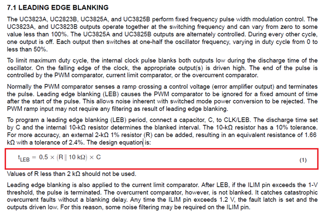
    UC2825 has programmable LEB as described in section 7.1 of the data sheet:

    Slope compensation is not needed in a bidirectional converter since the duty cycle is is limited to less than 50% per phase. For peak CMC, set up the current sense resistor as Rcs=0.95V/Ipk and again you can get an "ideal" value for Ipk from TI Power Stage Designer or else make the calculation yourself based on reflected secondary current, transformer mag current, Fsw, etc.

    Regards,

    Steve 

  • Steve, thank you for the super useful info. I have a few additional questions, and hope to bring a light to this UC2825B a bit more. 

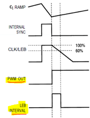
    Is the LEB frequency the same as the PWM frequency? I wasn't able to find any figure showing the relationship between LEB and PWM switching signals.

    I only use a single channel (Channel A) while leaving the OUTB open. Out of curiosity, how do we configure the phase shift between OUTA and OUTB?

    Is there a way to adjust duty cycle in the UC2825B? If not, what is the duty cycle then?

    Thanks, 

  • LEB is same as PWM/CS frequency. You don't phase shift OUTA wrt OUTB because they are asynchronous outputs which are clocked at 180° out of phase. The duty cycle limits you highlighted are the min/max limit capabilities of the PWM controller. Your actual duty cycle will be determined by your topology, power stage (transformer turns ratio), VIN_min<VIN>VIN_max and VOUT. If you don't want to work through the calculations, you can use TI Power Stage Designer to quickly sim the power topology and power stage and this will give you the min/max duty range you should expect.

    Steve