A related question is a question created from another question. When the related question is created, it will be automatically linked to the original question.
If you have a related question, please click the "Ask a related question" button in the top right corner. The newly created question will be automatically linked to this question.
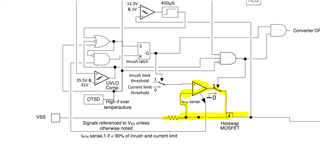
The inrush current is limited by internal current sensing resistor + amplifier + gate control. I think you may need external circuit to further do the inrush current limiting.
May I know why you need reduce inrush current? The PD inrush time is normally less than 80ms and PSE inrush current is smaller than PD's. Normally, there is no need to adjust the PD's inrush current limitation.
We want to reduce the inrush current to comply with the standard. The simplest way to do this is to use a fuse to interrupt the overcurrent at the time of failure, as other methods are complicated procedures. The product under development has low power consumption, less than 100mA in VPD, but inrush current is an issue in fuse selection.
It would be helpful if you could give us an example of an external circuit.
I can see IEC60601-1 is a standard for medical electrical equipment. I used to see some cases of using PoE in medical equipment, but I did not see an issue with PD inrush current (max 220 mA) before. Could you double check if the "inrush current" of IEC60601-1 stands for the same meaning of the "inrush current" of IEEE 802.3at-2009?
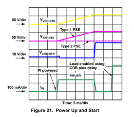
During PD inrush, the current charges the bulk capacitor, but the load is disabled. The load will be enabled after the inrush period. Since during PD inrush period, CDB pin of TPS2378 will be tied to RTN. You can refer to the I_pi waveform as shown below.
I cannot tell you any more about the standard, but it is specified as power, not as "inrush current".
Also, the Ipi waveform has been confirmed in the datasheet. The actual current values have also been confirmed with an oscilloscope, and there is no difference in our intention to suppress the peak of Inrush in Figure 21.
May I ask you to answer the question I sent you last time about the external circuit?
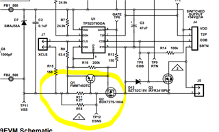
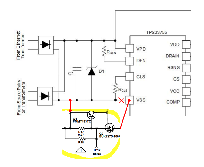
Yes, I think you can put it on the VSS side. Meanwhile, the gate driving circuit of this external FET should not influence the detection (19 - 26.5k) resistance & classification current. I am not an expert of current limiting circuit, so I also recommend you to reach out to real experts on that.
On the PD side, do you also need to disable inrush current limitation after the ~80ms PD inrush period? Since the current limiting circuit at the return loop will exist for the whole time, not only at the ~80ms PD inrush period.
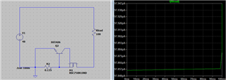
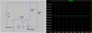
I tried to simulate it with the circuit you gave me, but no current flowed through the load. M1 and Q2 are similar parts because the original parts were not registered in spice.
Here, I was able to limit the current to about 130 mA by providing a resistor that connects to the 48 V line and changing R2 to 5 Ω, as in a typical constant current circuit. (This change was made because a large current flowed when R2 = 0.135Ω was left unchanged.)
Is this the correct circuit configuration? If not, please let me know the correct connection.
Also, if you are not sure, how can I contact your power management team?
Yes, you must have a pull-up circuit to control the Vgs. This Vgs control circuit cannot influence the influence the detection (19 - 26.5k) resistance & classification current (depending on what class it applies). I think 10k is too small to ignore the influence. You could use 100k.
I will forward your to the power design service team.
There are timing requirements for the in-rush current in the IEEE802.3.bt specification. If the in-rush current is reduced, the input bulk capacitance needs to be limited so it can be charged in the allotted time. I think it will be difficult to add external circuits to comply with the timing requirements. And as Diang said, it will need to be disabled after the in-rush period to allow for the steady-state current limit.
The TPS2375/76/77 have an Ilimit pin to adjust the in-rush current. These are PD controller only, so a separate PWM IC is required to control the converter.