Other Parts Discussed in Thread: LM5177
Hi Texas Team,
We are using LM5118Q1MH buck boost for our product.The input votage of the converter is getting from two different cases.
1.When power on,Input voltage is taken from AC-DC module conveter output which we are used --->input voltage of the buckboost will be 58V
2.When power cut,Input voltage is taken from the battery(For secondary power support).This battery backup will be used for only 5 mins --->Input voltage range of the buckboost will be 39 to 54.6V.
But 90% of the time our product will be powered up by the AC-DC module.If we are designing the switcher with the first case of input voltage range(57.5 to 58.5V),Efficiency will be come around 96.6%.If we are designing with the second case of input voltage range(39 to 54.6V),Efficiency will be come around 92.1%.Due to this Efficiency reduced in second case,we are getting 13W dissipation for this switcher.
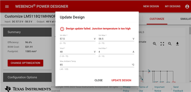
Also we have to simulate the converter with the 85 deg ambient temperature but we could able to run the simulation with 54 degree ambient maximum, it was showing junction temperature overlimit error. Could you please confirm the efficiency,power loss and which input voltage we have to keep for simulation for this buck boost converter?
1.96.6% Efficiency without error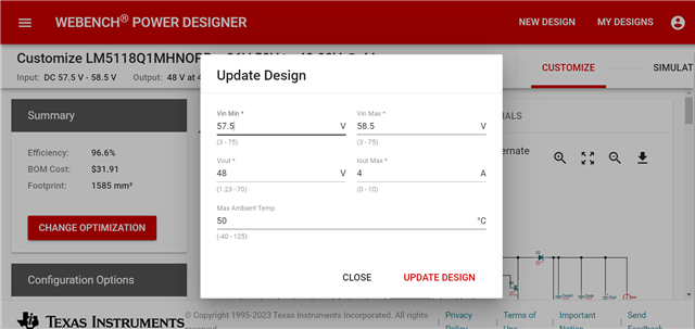
2.Error is show up when put 85deg ambient temperature.