This thread has been locked.

If you have a related question, please click the "Ask a related question" button in the top right corner. The newly created question will be automatically linked to this question.

TPS92520-Q1: output current accuracy calculation need some detail data

Part Number: TPS92520-Q1

Hello expert,

     I'm trying to calculate the output current accuracy, some detail data of this device need your help.

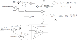
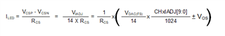
    1.What is the tolerance of the 10k and 140k resistor? I think it will impact the "division by 14' performance. 

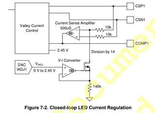
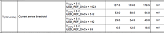
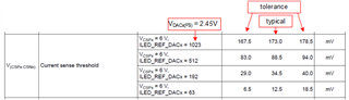
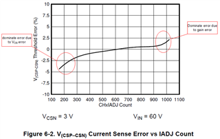
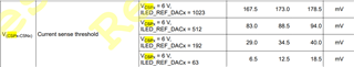
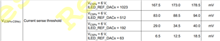
    2. what is the tolerance of the offset voltage between CSP1 and CSN1?I think it also impact the output current accuracy calculation.

  3.Is there any bias current via CSP1 and CSN1? It is missing in the datasheet but I think it also impact the calculation.

  • For question 2,has the offset voltage impact been consider in the current sense threshold below?


  • Hello Zhiyuan,

    1) The tolerances on each resistor in the divider can be fairly high, but they are matched resistors so the ratio is tightly controlled, which is what is important.

    2) This is a forced offset that is only done at the start of turn on to ensure it starts up.  There is an offset voltage on the V-I converter amplifier and that can be positive or negative, therefore we force the offset to ensure that the signal in the control loop is positive at the start of the turn on sequence.  It gets bypassed once the current is high enough to make the signal positive. 

    3)  input bias current are insignificant compared to the resistor divider and doesn't contribute significantly to accuracy.


    Each part is tested to ensure that it meets our +/-4% accuracy at full scale. 

    -fhoude

  • Hello fhoude,

        Do you mean the V(CSP-CSN) in datasheet includes all the tolerance of the device, so we just need to add the Rshunt tolerance to consideration also,and we will get the total output current accuracy?

        Here is my calculation base on this understanding, pls check, thank you!

  • Hello Zhiyuan,

    Yes, this it is correct that control loop is tested at ATE and that the only thing you need to adjust for is the current sense resistor tolerance.  Keep in mind that is just one test conditions of 6V on the output and at 24Vin, but the  limits are over process and temp.  You will see that at lower DACx setting the % error increases.  This is expected, because as the voltage on the V-C converter input pin gets smaller, the off set voltage (Vos) of the amplifier become a larger ratio of the signal controlling the loop.  I have included a diagram that shows basic calculations for the loop.  


    In the datasheet we can see that on figure 6-2, where at lower CHxIADJ Counts (Which sets VIADJ in about diagram by programming of DAC) the % error starts to drop quickly.   There are other sources of error, like gain, which might not be linear.  Generally speaking the gain error is more dominant at higher CHxIADJ counts.  You may want to center  your CHxIADJ based on typical value of ~600 because the % error is lowest there and makes the % error distribution more centered.  See figure 6-2 below.  

    You can address Vos in the effects by the following generalized equations.  

    Please send me the actual excel spreadsheet so I can look at it to verify.  You can send it via email if you worried about proprietary information.

    -Francis Houde

  • Hello expert,

        According to figure 6-2 you mentioned,count ~600 share the lowest %error. But according to datasheet below,the higher count share the lowest % error. They seems to be conflict? Which information should I use?

        And you said this data is base on Vin=24V and Vout=6V. So what is the impact on output current accuracy if the Vin and Vout change? 

  • Hello Zhiyuan,

    The ATE test data shows that the best accuracy is at full scale, but you have to keep in mind that the limits are 6 sigma.  This data is a summary of the distribution of many tested parts with extra wide guard band that considers process and temp. 

    Figure 6-2 is the assessment of one part showing the general curvature of the device over the CHxIADJ range.  I would use the ~600 CHxIADJ of the ATE typical test data as the location to center my accuracy for each part.  

    -Francis Houde

  • Hello expert,

        That is to say for output current accuracy calculation, we should use the data below,and no need to care the figure 6-2,am I right?

  • Use the ATE data for accuracy but know that is super conservative and 6 sigma boundry limits.  The figure is to help with centering for calibration to minimize errors over all set points.