


Other Parts Discussed in Thread: BQ24297
We are currently designing and testing our pcb that has bq24298 pmic charger and usb type c connector. Basically, bq24298 supplies 3.3-4.2V to LDO that supplies 3.3V@150ma to our microcontroller. Our system has standard 14500 800mAh battery with 10K NTC (@ 25C).
Last Thursday, I experienced a problem while connecting our pcb to charge battery from one standard usb port of my notebook. Basically, my pc broke after this event (it suddenly powered off and I never could power on again)!
During this test, I don’t remember very well if the battery was connected to the pcb.
Now I have a series of the questions below:
1)I use these parameters of the bq24298 I2C registers, to be able to charge battery in two hours (so we want to charge at 400mA-500mA per hour), and in any case we DON’T want to use otg future (we don’t want to use our system as a powerbank, so in any case we will output voltage to outside as maybe this was the reason why my notebook broke).
REG00 = 0x32
REG01 = 0x1A
REG02 = 0x00
REG03 = 0x11
REG04 = 0xB2
REG05 = 0xCC
REG06 = 0x73
REG07 = 0x4B
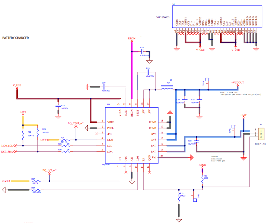
Can you review these registers and schematic below for our application?
After read again the datasheet, and see sch of the evb we applied following changes that we think are vital for correct function of the pcb and external charger.
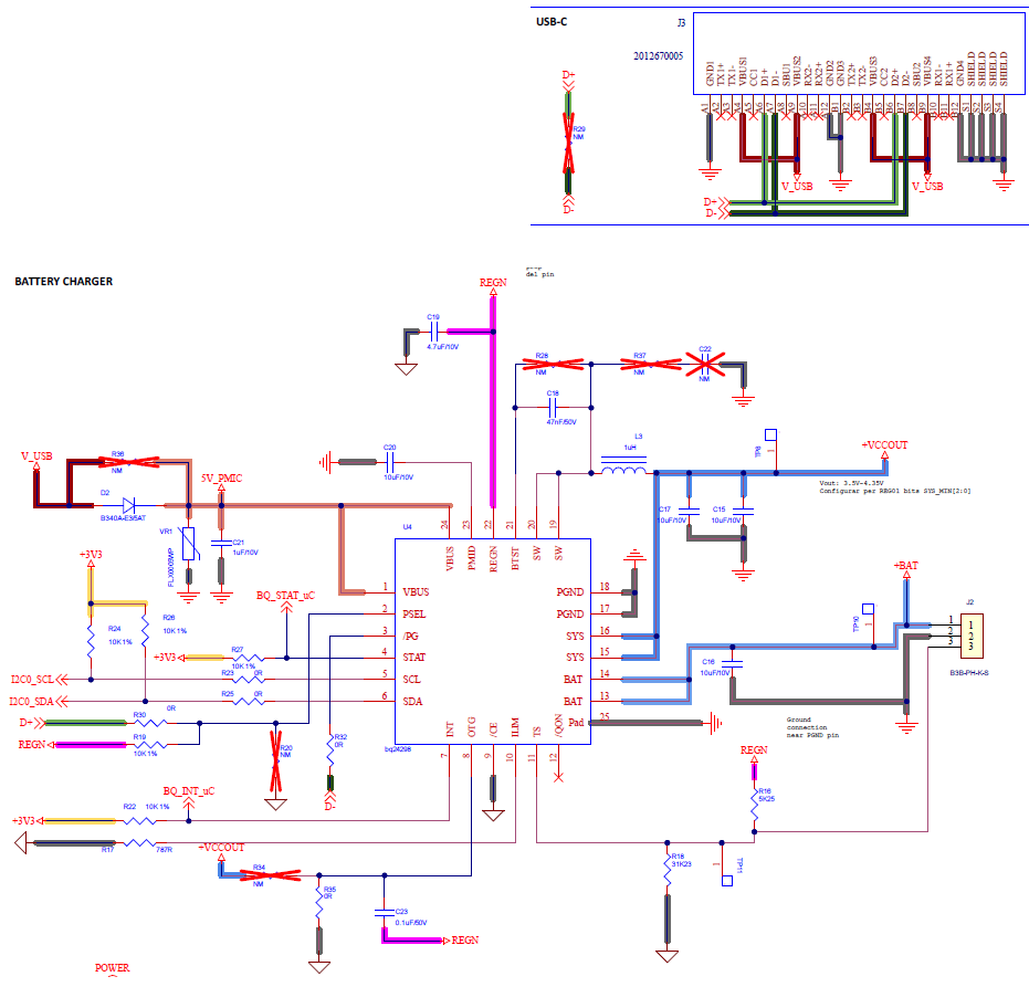
2)Do you have some schematic/application note that explains how to connect usb type c connector to the bq24298? If not could you help us to connect usb type c with bq24298? (basically how we should force lines of usb type c such as CC1/CC2/ TX/ RX and so on).
3)My last question is about charge level of the battery. I see in datasheet is it possible to know state of the charge during charging, but is it possible to know percents of the charge during the charge? Also, what about percentage of the battery without charger?

