This thread has been locked.

If you have a related question, please click the "Ask a related question" button in the top right corner. The newly created question will be automatically linked to this question.

UCC14140-Q1: Looking for the reference for single output system configuration.

Part Number: UCC14140-Q1
Other Parts Discussed in Thread: PMP23223, UCC23313, UCC14240-Q1

Dear TI experts,

My customer considers UCC14140-Q1 for their new product.

In the datasheet we can find about single output system configuration as below picture. (figure 9-9, page 38)

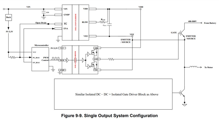
but I cannot find any other information about schematic, layout, the name of MCU and gate driver and so on.

Could you give me more information about this configuration? like I said, it would be very helpful if you give me schematic, layout, or the part name of other parts.

Please check this issue. Thanks.

Best regards,

Chase

  • Hi Chase,

    PMP23223 is an example of how to use this for a single-ended output. 

    Does this answer your question?

  • PMP23223 is a typical example of a dual output configuration (+18V/-4V) used to bias a gate driver for IGBT/SiC and most TI IIB (Integrated Isolated Bias) modules are configured this way. We do not have an example of a single output only configuration. However, the UCC14130EVM-070 is configured for dual positive output voltages (+12V/+5V) and includes a jumper (R8) to easily be configured for a single output. Any IIB module can be configured for single output. The key difference for single output configuration is to short the two feedback pins together and connect RLIM directly to VDD and this is discussed in section 4 of Application Note SLUAAH0.

    The other questions asked about the μC, gate driver etc, have nothing to do with whether the IIB module is configured for single or dual output. The μC for example, is providing the PWM control, gate drive pulse, enable and fault response and could be any μC or analog PWM controller. The input voltage, isolation requirement, gate driver and load (SiC/IGBT/GaN) will determine the configuration and type of IIB needed.

    Also, all the IIB modules have Excel Design Tools available in the product folder.  

    At the bottom of the spreadsheet, click the tab for "Single Output" and you will see the schematic and calculations for optimal configuration.

    Regards,

    Steve

  • Dear JCHK, Steven,

    Thank you for your support.

    Finally my customer drew first schematic with UCC14240-Q1 and UCC23313. Could you review this schematic?

    Please let me know if you cannot review UCC23313. I will post another thread.

    DCDC_SCH1.pdf

    Best regards,

    Chase

  • HI Chase,

    It looks like they have it setup properly to support 15Vout. For the UCC23313 you might want to post another thread for the HPD team to confirm.

    Regards,

  • Dear JCHK,

    Thank you for your support.

    I confirmed that customer drew the schematic with the intention of 15V output. then any other schematic looks good? please confirm it again.

    and here is more question about RLIM pin.

    my customer wants to make single output, so RLIM pin is floated.

    - Is it right drawing? or should it connected to GND or VCC?

    Please check this issue. Thanks.

    Best regards,

    Chase

  • HI Chase,

    For single-ended operation, RLIM is referenced to GND.

    Regards,

    John