- Ask a related questionWhat is a related question?A related question is a question created from another question. When the related question is created, it will be automatically linked to the original question.
This thread has been locked.
If you have a related question, please click the "Ask a related question" button in the top right corner. The newly created question will be automatically linked to this question.
I would like something like a variable LDO for battery operation.
I have a battery powered application that would work fine from 5V down to 3.0V.
Each of the two series batteries will produce from 3.5 to 2 volts before exhausting the battery at it's operating mAh
So the two batteries in series will start at 7.0 volts and operate down to 4V.
I have LEDs and a Microcontroller work just fine from 5V to 3V.
What I want an LDO like device that will provide 5 volts output as long as it can and then operate down to 3 volts.
I would rather not a a number of diodes inline with the supply voltage.
Is there any TI item that can help with this?
Hi Michael,
I want to clarify first, you need an LDO that can do 7V->5V while the batteries are at full charge. Then, once the charge of the battery goes lower, the LDO will need to regulate 4V->3V, correct? What is the load current?
If you are needing an adaptive LDO, we do not have this in the market; however, there are adaptive LDO output circuit designs that have been made in the past.
Such as this example here.
It might be possible to sample the battery voltage and adjust the LDO output in this way. One LDO which might be a good candidate, depending on output current of course, is TLV75801PDBVR since it has a feedback pin.
Regards,
Andres
Hi Andres,
Thanks for the feedback.
The current draw is 140mA ma, 65mA min, and very little in standby (maybe 2ma).
And yes, the idea is that the regulator puts out 5V with 7V input from the battery. And then when the input voltage is above 5 volts, but not above the LDO voltage the output voltage starts to decrease from 5V out to 3V out based on the battery voltage.
I will go look at the link and get back with any questions.
Thanks again
The TLV75801PDBVR could be promising.
The link in "this example here" gave me a page not found error.
Is there another link?
Hi Michael,
Sorry about that, I am looking for a link which could show the concept I mentioned, but couldn't find another link. I will write down some examples with the TLV75801PDBVR as a concept design and share it here for you by tomorrow!
Regards,
Andres
Hi Michael,
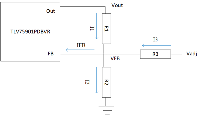
For TLV75801PDBVR you would need a feedback resistor network with a variable voltage input, which you can see on one of the sides of R3 as Vadj on the diagram below:

There are some variables here which are known through the datasheet such as VFB = 0.55V and IFB = 10nA. The rest of the values will be set by the needs of your system.
I1 = (Vout-VFB)/R1
I2 = VFB/R2
I3 = (Vadj-VFB)/R3
By KCL we know that IFB = I1 - I2 + I3 , which we can use to adjust the resistor values and Vadj depending on the desired Vout.
If you solve for Vout, we can get the following formula:

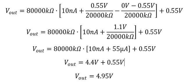
If you use this formula and set R1 = 80kΩ, R2 = R3 = 20kΩ, and Vadj = 0V you will get the following:

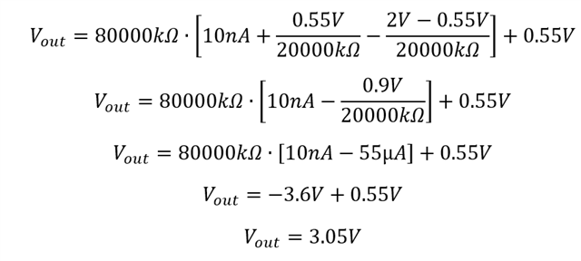
If you keep the same parameters and change Vadj = 2V you will get the following:

Regards,
Andres