This thread has been locked.

If you have a related question, please click the "Ask a related question" button in the top right corner. The newly created question will be automatically linked to this question.

LM5156H: LM5156H

Part Number: LM5156H
Other Parts Discussed in Thread: LM5156

Dear TI team, 

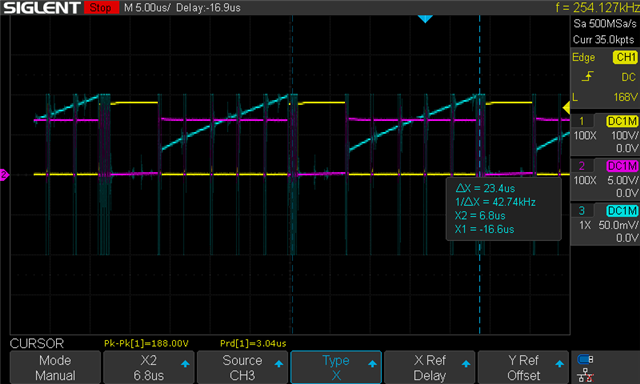
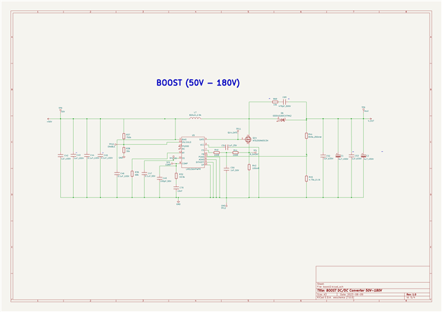
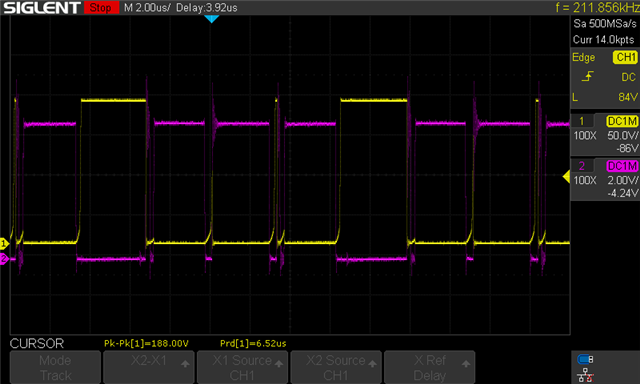
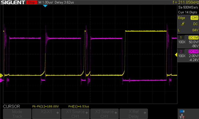
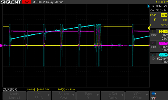
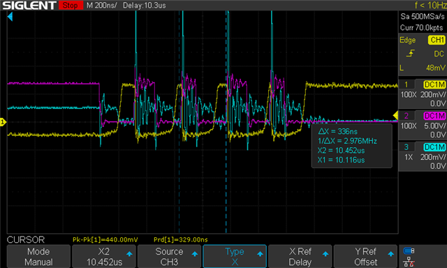
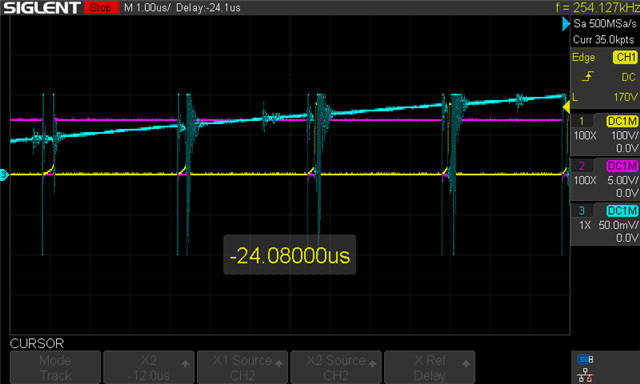
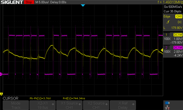
I've designed a boost converter using the LM5156 IC with an input voltage of 50V, output voltage of 180V, and an output power of 30W. The converter's frequency is set at 330kHz, and it employs peak current control. The expected duty cycle is around 0.75. However, I'm observing a peculiar behavior where the correct PWM waveform is not established in a single switching cycle. Instead, there are about five consecutive cycles where the duty cycle is almost at maximum (around 0.95), essentially not turning off the transistor. Following these, there's an entire off-period. If the PWM were averaged out ignoring the quasi-leading periods, the frequency seems to be around 40kHz, not the set 330kHz. It's as if the converter is exhibiting variable duty cycle operation. Although the output voltage does reach the expected 180V, the behavior appears anomalous. Interestingly, after the five quasi-leading cycles, the inductor current reaches the target 1A, at which point the PWM state should ideally toggle. Could the issue potentially be related to slope compensation, or is the rate of rise of the inductor current too gradual?


  • Hi Harun,

    thanks for using the E2e forum. Can you please share the schematic of your boost converter design?

    Did you check your design already with the quickstart calculator? It can be found here: https://www.ti.com/tool/download/SNVC224

    Also, can you please label your measurements? To clearify which waveform is measured at which point. I am looking forward hearing from you.

    Best regards,

    Moritz

  • Hi Moritz,

    yes, during the design, I used the quickstart calculator.
    Measurements: Yellow signal - Vds of the transistor, pink signal - control signal, blue signal - measured voltage with a shunt resistor placed in series with the transistor. Additionally, I am sending you the electrical schematic.

    Best regards, 
    Harun

  • Hi Harun,

    Thanks for the claification and the schematic. Can you please try to reduce the current sense resistor to 50 or 25m and take the measurments again? I would like to see if this is a current limit problem.

    In addition i would like to see a more zoomed in waveform of the turn off phase in a normnal switching cycle and of the fast switching, right before it stops switching.

    Best regards,

    Moritz

  • Hi Moritz,

    I've already tried with a 25m current sense resistor, and it seems like there is the same problem. There are the results (pink - control signal, yellow - Vds of MOSFET)

    Also, there are zoomed waveforms (100m current sense resistor): 

  • Hi Harun,

    Thanks for the additional scopeshots.

    Can you please try to increase the load to maybe 0.3 to 0.4 A and decrease the load to 80-100mA? Please take scopeshots for both cases.

    Another question: What is the reason you use such a big inductance?

    Best regards,

    Moritz

  • Hi Moritz,

    I'm sending you signals for the case with an output load of R=1.63k which results in an output current of Iout=0.11A (pink signal - control signal, yellow signal - output voltage). Unfortunately, I was unable to test the converter for an output current of 0.3A due to the lack of a small load on the output. What can be concluded for the case of an output current of 0.11A is that we have a variable number of conduction cycles (5-2-3-3-2).

    Indeed, based on the calculations for a inductor ripple current of 30%, we get a slightly lower inductance value (L=613μH). To reduce the ripple, a inductor with a slightly higher inductance was used. Do you suggest that the inductor design might be critical in this case?

    Best regards,
    Harun

  • Hi Harun,

    Thanks for the measurements. It would be great if you wold be able to take a measurement with higher output power as well.

    Can you in addition please measure the voltage at the current sense pin and at the feedback pin please?

    It is possible that the inductance has something to do with the issue, are you abble to try out a smaller inductance?

    Best regards,

    Moritz