


Other Parts Discussed in Thread: BQ24298
This thread is continuation of the previous thread
For our application, we decided to mount BQ24297 that supports direct D+/D- usb connection.
We want to charge Standard 800mA 14500 battery at 400mA/h using usb type c connector. In any case, our device WON’T output voltage to outside (as an powerbank). bq24298 supplies 3.3-4.2V to LDO that supplies 3.3V@150ma to our microcontroller
Can you review our schematic?
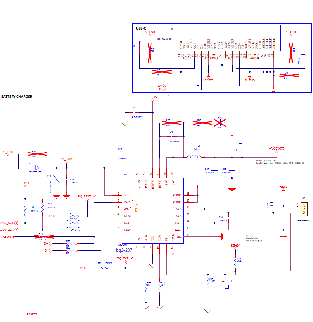
Couple of notes!
1)Diode D2 only is need to prohibit giving voltage to outside, but if the design will be stable this diode can be unmounted and shorted.
2)USB type C has signals such as TX1+ / TX1- / RX1+ / RX1- / SBU1 / SBU2 that we left unconnected, we think these signals are not needed as they are used for high speed communication.
Do you know if some charger may need some signal to be forced with some voltage (as we can’t connect these signals anywhere, only thing we can do is force them)?
Keep in mind, our application is very low speed charging, so we hope proper usb negotiation is done only by D+/D- pins connected to bq24297.
3)We don’t know about if we need to force CC1/CC2 pins, just for a case we left two voltage divider resistors at each pin.
4)The I2C registers configuration will be the following:
REG00 = 0x32
REG01 = 0x1A
REG02 = 0x00
REG03 = 0x11
REG04 = 0xB2
REG05 = 0x9C
REG06 = 0x73
REG07 = 0x4B
