This thread has been locked.

If you have a related question, please click the "Ask a related question" button in the top right corner. The newly created question will be automatically linked to this question.

LMR33620: Vout=Vin

Part Number: LMR33620

Hello

It seem to me that I have the same problem.

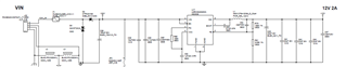
In my prototype with LMR33620ADDA, connected as per the schematic below, Vout is always equal to Vin.

With Vin =24V I don't see any short circuit, but it is not working properly

  • Hi Daniele,

    I don't see any immediate issues with the schematic. The CFF capacitor is not needed for your design as is, but it should not be causing the issue you are describing. Can you share any oscilloscope screenshots and a photo of the test setup?

    Best regards,

    Ridge

  • Hi Ridge,

    below I send some picture of the setup and oscilloscope. PG is never at "high level". Sw seem to be at the same level of Vout. If I rise Vin up to 28V then I see a short circuit and probably the LMR33620 is damaged ( if it is removed there is no more short circuit). Current in the input was limited to 30mA. It seem that the LMR66230 is not working at all.

    Thank you for your support

    Daniele

    Setup:

    PG(A1) vs Vout

    SW(A1) vs Vout

    Vin(A1) vs Vout

  • Hi Daniele,

    When you say the current is limited to 30mA on the input, is that a setting of the power supply? For a 2A output at Vout=12V and Vin=24V, the device will need more than 30mA of input current to function. Input current for a buck converter is:

    Also are you seeing the device function properly at 24Vin, then improperly at 28Vin? I'm not sure what you mean by "if it is removed there is no more short circuit."

    Best regards,

    Ridge

  • Hi Ridge, 

    yes the limit of 30mA was a setting of the Power supply. Is the first time powering up these prototypes, so I wanted to be sure there is no electrical problems, such as short circuits, before increasing the power supply current. Also, there was no high loads connected and the board was sinking 20mA (LEDs, LDO...).

    At Vin=24V the device doesn't work (Vout is 24V instead of 12V).

    If I increase Vin at 28V, the Power supply voltage drops and the board sinks the limit of 30mA, so there must be a short circuit and probably the problem was inside the LMR33620, because when I removed the LMR33620 from the board the sinking current was much lower.

  • Hi Daniele,

    As you are describing, the issue seems to be an electrical over stress on the device. Your schematic and components look ok with their power ratings. Could you share your layout for the device? We need to check if the issue is layout related.

    Please provide images of the different layers of the PCB.

    Best regards,

    Ridge Lahti

  • Hi Ridge,

    I checked the layout.

    There is one error related to the thermal PAD: there is no stencil opening under the thermal PAD, so thermal conduction is very poor. But anyway I would be surprised if this is the reason for the LMR33620 not working at all.

    Here are the layout images:

    top:

    Inner1 (GND)

    Inner 2 (VCC)

    bottom:

    Thank you

    Regards,

    Daniele

  • Hi Daniele,

    The thermal pad connection to ground plane is required for the device to achieve good thermal and electrical performance. For the HSOIC package you are using, the thermal pad also acts as the AGND pin which is the ground reference for internal reference and logic. Please connect the thermal pad and test if the issue persists. I have attached a screenshot of the layout example from the datasheet: https://www.ti.com/lit/ds/symlink/lmr33620.pdf

    Best regards,

    Ridge Lahti

  • Hi Ridge,

    I've managed to connect the thermal PAD to the board. Now Vout level is at the desidered level of 12V. Now I will test the board with the expected loads, but for sure the problem I was seeing is no more present.

    Thank you very much fro your help.

    Regards,

    Daniele