Other Parts Discussed in Thread: TPS62110, TPS40210
we are using the TPS40170 as the input DCDC to lower 18..33VDC (nom. 24..28) to 9.2V.
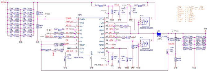
The 9V2 are used to generate 5V via TPS62110 and 20V via TPS40210. Both, the 5V and the 20V are used to power simple push-pull power supplies. As these push-pull supplies do not have a softstart, they produce some current peaks on start-up on the 5V and 20V line (normally "behind" their 5V and 20V regulators).
While the TPS40170 starts w/o issues under normal conditions, as soon as these current peaks by the connected push-pull power supplies occur on the 5VDC or the 20VDC, the controller seems to trip an OCP and stops operation of the external switches. This causes a drop in the internal 9V2, a reset on the Push-Pull and some sort of hiccup. Somtimes the electronics manage to start, sometimes the hiccup is infinte.
The issue occurred first with one of the three PSU on the 5VDC with higher voltages (>29VDC) and it gets worse the more push pull PSU are activated. Lowering the input voltage allows more Push-Pull PSU to be connected.
I did some measuerements showing the gate signal (but with the standard 3inch GND connection on the probe) of the lower transitor increasing in pulse width with the push-pull power supplies starting operation and stopping after round about 7 cycles, thus, I assume an OCP error is detected. Unfortunately, I cannot do a measurement of the current monitored by the TPS40170. There is also less to no chance to measure the inductor current as all is SMD and soldered to some copper areas on the PCB - giving good connection but als draining any heat applied by solver iron :-|
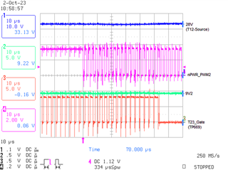
(nPWR_PWM2 is the push-pull power supply signal, T23_Gate is the Gate signal of the lower transitor).
My assumption is that either some noise on any monitored signal is tripping the protection function or the problem might be related to the issue, that the M/S pin is left floating while the TPS40170 must operate as Master. That seems to be a difference to the datasheet... Nevertheless, everythins seems to starts even being set to slave mode w/o having no signal on the SYNC (on the PCB there is just the Pad w/o any traces, which makes it difficult to connect M/S to VIN to get the TPS40170 set to master mode - but if this would be the root cause we have to add some hardwire).
Do you see any issue in the schematic or can suggest any modification to get the TPS40170 stable over the complete input voltage range (18..33VDC)?
KR, Carlhermann
Note: as the layout is very compact and all SMD, measurements beyond voltage / signal check by scope maybe diffcult, but if any measurement helps to solve the issue, let me know.