This thread has been locked.

If you have a related question, please click the "Ask a related question" button in the top right corner. The newly created question will be automatically linked to this question.

LMR14020-Q1: LMR14020

Part Number: LMR14020-Q1
Other Parts Discussed in Thread: LMR14020

Hi Team,

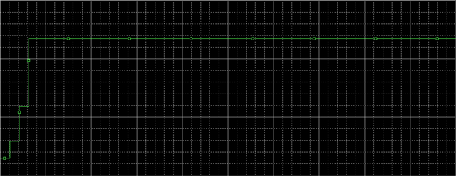
I am using LMR14020 ic in my design. During simulation waveform across RT pin is not as per expected result. Please find below screenshot for your reference.

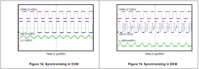
As per data sheet it should be like square wave (for 1amp load). 

  • Hi,

    The waveform in the datasheet is the waveform of the RT/SYNC pin when the synchronization signal is supplied externally. At this point the waveform should be the same as the external clock signal, so it's a square wave.

    During simulation, this pin is connected to ground through a resistor. You can change the frequency by adjusting the resistor value. At this time, the RT voltage is high level, just like what you simulated. Thanks.

    Aurora