Other Parts Discussed in Thread: PMP31179
I cannot see any major difference between PMP31179 and PMP30763 which may affects harmonic emission greatly.
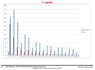
However PMP31179 much worse than PMP30763 at 800Hz DO160 Harmonic test.
Could you please tell what I missed?
PMP31179
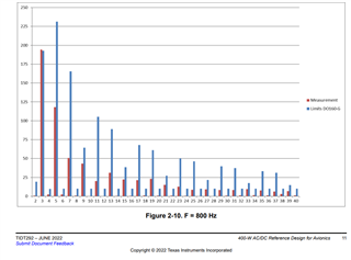
PMP30763