Other Parts Discussed in Thread: TPS92640
Dear TI team,
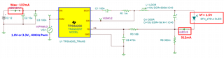
Can you please check the TPS54200 converter output voltage below conditions?
(1) Vin : 12V
(2) Vout : 1.7V , Iout : 0.6A
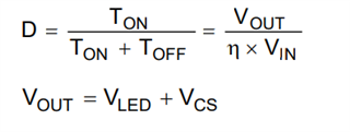
When I calculate duty, it is approximately 14%.
It is approximately 10%, so I would like to inquire whether stable Output voltage is possible.
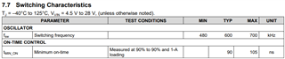
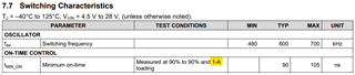
If you expect the Max Duty Cycle and Min Duty Cycle of the TPS54200 Chip, are they as follows?
Duty(Max) = 100(%) - Minimum on Time(typ) / ( 1 / Switching Frequency(typ) ) = 100% - (90ns/ (1/600kHz)) ≒ 94.6%
Duty(Min) = Minimum on Time(typ) / ( 1 / Switching Frequency(typ) ) = (90ns/ (1/600kHz)) ≒ 5.4%
Could you possibly assist me with the values of minimum duty cycle and maximum duty cycle?
Best regards,