This thread has been locked.

If you have a related question, please click the "Ask a related question" button in the top right corner. The newly created question will be automatically linked to this question.

TPS55340-EP: Frequency foldback with load

Part Number: TPS55340-EP
Other Parts Discussed in Thread: TPS55340

Hi,

I have designed a boost converter to generate 20V from a 12V bus. The nominal load will be between 150 to 75-ohm. I have used the reference design tool "TPS55340_BOOST_CALCTOOL_REVC_EDIT_v2".

Vin 12 V
Vout 20 V
Iout_max 260 mA
f_sw 600 kHz

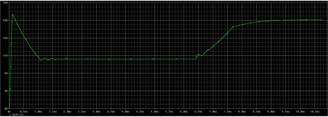
I have run simulations with Pspice with the TPS55340 under nominal load and the result is this: 

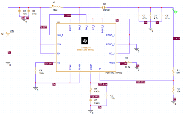
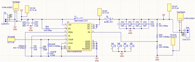
The selected components are:

CO1,CO2,CO3,CO4 4.7-uF C2012X7R475K125C
CCOMP 0.22-uF GRM155R61H224KE01D
CHF 120-pF C0402C121K5RACTU
RCOMP 4.42-kOhm ERA-2ARB4421X
RSH 154-kOhm RP73PF1E154KBTD
L1 150-uH SRR1050HA-151Y
D1 B540C-13-F
RSL 10-kOhm RP0402BRD0710KL
U1 TPS55340MRTETEP
CIN1 10-uF GRM188R6YA106MA73D
CIN2,CO5 0.1-uF GRM155R71H104KE14D
RFREQ 78.7-kOhm CRCW040278K7FKED
R5 50-OHm RP73PF1E154KBTD

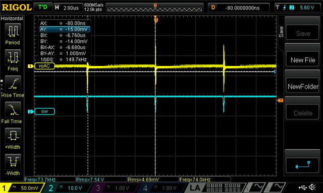
When a load is placed at the output, I am testing the "SW" pin and I can see the frequency drops from 600 kHz to 150 kHz and the IC enters in frequency foldback. This is due to overcurrents but I don't see where this overcurrent can be coming from. I have checked the inductor saturation current and its well above the recommended from the design tool. What I can see is that the voltage drops for higher load currents. For a 10-kohm load resistor the converter works just fine but when I place lower and lower values the voltage keeps dropping until I see the 12V input.

I hope there is enough information for you to understand my problem.

Thank you,

Jordan

  • Hi Jordan,

    Thanks for reaching out and for the detailed description of the schematic parts. I'll look it and give you some feedback.

    Thank you and best regards,
    Bryan

  • Hi Jordan,

    Excuse me for the delayed response. When I use the calculator tool you mentioned, I get different values for the parts in the compensation circuit.
    Namely Ccomp=470nF, Rcomp=619Ohm, Chf=820pF.

    Could you please tell me more about the way you calculated the parts from the compensation loop?
    Did you calculate your bandwidth based on the switching frequency, the right-half-plane zero or using the gain-bandwidth-product of the error amplifier?

    Furthermore, it's important to indicate that while the calculation of these theoretical values of the compensation loop elements is a good starting point, the actual tuning should be done inside of the lab, as parasitics arising from component placement and PCB routing are uncertainties which can only be solved experimentally. 

    Thank you and best regards,
    Bryan

  • Hi Bryan,

    Thank you for your response. I have noticed there are different versions of the excel tool. The one I used gave me different values from the excel tool there is now in the component webpage. I am attaching you the file I used with the values I selected in case you want to check it. Maybe I should try with the values from the updated version of the tool and see if it solves the problem. However I don't see why it shouldn't work at all with the old version.

    I have also noticed the system is unstable with the current values. Increasing the output capacitor may solve the problem. I will try.

    Thank you very much!

    TPS55340_BOOST_CALCTOOL_REVC_EDIT_v2.xls

  • Hi Jordan,

    I've seen you changed the value for the Cout derating percentage to 120%. This could possibly cause problems around stability.
    Please keep it maximally at the standard 100%, like default in the Quickstart Calculator.

    Thank you and best regards,
    Bryan