This thread has been locked.

If you have a related question, please click the "Ask a related question" button in the top right corner. The newly created question will be automatically linked to this question.

LM76005: Input/output capacitance, Long Soft-Start for Power Limiting

Part Number: LM76005
Other Parts Discussed in Thread: TINA-TI, , , INA215, LM5069, TIDA-010070, LM5164

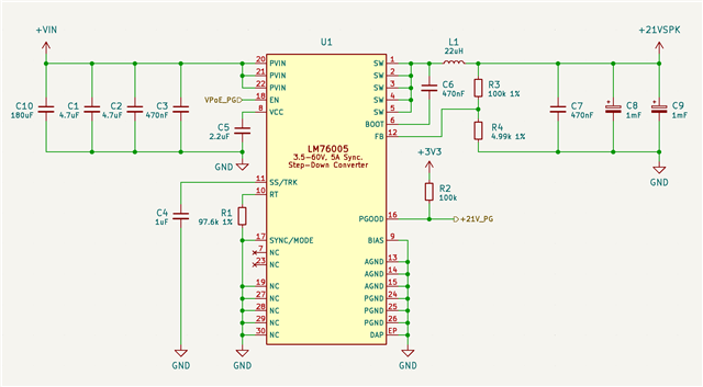
Hello. We're working on a design based upon the LM76005. We have a few interesting constraints that I would like some suggestions on.

  1. The device is a PoE PD, so we need to minimize input capacitance seen by the PSE during power negotiation. Ideally to something like 10-22uF. I can't simulate startup in Webench, and export to TINA-TI is broken – so I haven't been able to validate this.
  2. We'd like to maximize bulk output capacitance (ideally, 1mF). Initial load on the device is very limited at startup (<1W). Downstream loads are switched in and out, and have individual slew rate controls. Assuming we control soft start, are there any problems with this amount of capacitance?
  3. We need to limit the inrush current (presumably using the LM76005's soft start function?) so that it doesn't exceed 24W. If I'm thinking about this correctly, with our bulk output capacitance, this requires a soft-start of ~0.5 seconds, which seems much higher than anything the datasheet mentions. Are there any problems with this approach? Any other suggestions?

Thanks for your assistance!

  • Hello,

    1. If the question is how much input capacitance is needed, then the datasheet recommends a 2 x 4.7uF 100V rated capacitor on the input. Refer to 8.2.2.4 in the datasheet. This should meet your desired input capacitance spec and not be an issue for your design and is the recommended components on the LM76005EVM. If Webench doesn't work for your evaluation purposes, I would suggest  the LM76005-Q1 PSPICE unencrypted transient model on the product folder:https://www.ti.com/product/LM76005-Q1. If that doesn't meet your evaluation needs, then I would recommend ordering an EVM for bench evaluation to your desired application. 

    2,3. For this large of a output capacitance you may want to implement a load switch in series with the DC/DC buck converter too implement a slew rate control and manage inrush current. Please refer to section 3.3 of the app note.

    Regards,

    Jimmy

  • I'm working on bringing the design into PSPICE for TI (which includes the model) – but also good that the unencrypted transient model is available, since I wasn't able to find it before!

    With regard to 2,3: is it correct to say that you are suggesting adding a load switch to the output of the buck converter, managing inrush of the large bulk capacitance, rather than using the LM76005's soft start function to control this? This might work for this application. Presumably a bi-directional load switch? For +21VDC, any suggestions from the TI lineup?

    Edit: realized I can just use a low-side load switch, here. But the recommendation question still stands!

  • Hi,

    I was concerned that the slow soft-start might be so long (0.5seconds) that the device thinks it's has a short circuit fault condition. 

    I would suggest testing this on an EVM and adjusting the  SS/TRK softstart time to slow down the inrush current from the large output capacitors.

    Regards,

    Jimmy 

  • Is there any way that I can get someone at TI to test or better verify this for me; we're on a tight timeline right now, and if there's undefined behavior in this part, I would prefer that TI can get to the bottom of it in a well-equipped lab.

  • I will need to order a sample EVM from the TI store which takes at least 3 - 5 business days. 

    I may be able to provide results by middle next week.

    Does this work for your timeline?

  • Yes – that would be very helpful. For what it's worth, we are using *mostly* TI components in our current work – hopefully we will make this up to you in order volume.

    Generally, we would like to limit power to 14W on startup. V_in is expected to be 42-58V. V_out should be 21V. Ideally, we'd like to see up to 1mF of output capacitance – so whatever soft start time is necessary to limit power at or below that level would be excellent. I'd also be curious to see your calculations.

  • Thanks for the update, for now the earliest I can get to this bench evaluation is next week when the boards should be coming in.

    I will keep you updated on the results when it comes in. 

  • Much appreciated! I'll look forward to your response.

  • No problem. Currently getting the logistics of getting the EVMs right now. 

  • I have an alternate proposal for you that might simplify this: would your team be willing to provide me with a design to perform current limiting during inrush using a current-sense amplifier (perhaps the INA215?) and op-amp on the feedback pin? We would want to limit to the inrush current as suggested in previous messages. What do you think?

    In simulation, the LM76005 does *not* like long soft starts – and I suspect we'll see the same behavior in the lab.

  • Hi,

    You can implement the CC circuit shown in app note SNVA829. Though this is a CC/CV implementation on the output, I would imagine that the sense resistor, amplifier and voltage regulation circuit (Vz) would apply on the input here as well. 

    I think the main way to limit inrush current aside from using the built in soft-start feature of the LM76005 is to use a load switch (see app note SLVA670).

    My suggestion would be to implement both LM76005 soft-start and a load switch to provide the best inrush current reduction.

    Regards,

    Jimmy 

  • These are good tips; however, I don't see a suitable load switch in TI's portfolio. It would be really helpful if I could convince you guys to do a little legwork here to come up with a working solution. We're thrilled about the LM76005, but we'll probably have to end up switching to a different vendor with something that works out of the box if we don't have high confidence in a solution on the first rev. If you can help us out with the design work a bit, here, it would certainly make it easier for us to justifying staying with this part.

  • Hi,

    I am trying to consult with our internal power design service team to see if there are any recommended system level approach to this.

    It may come down to using a hotswap controller on the input which is generally meant for limiting inrush current. However I would like to point to an existing TI reference design. Please give me some time to gather more information on this system requirement and provide the appropriate solution.

    Regards,

    Jimmy

  • I'd definitely appreciate that. We are very tight on time, at the moment. Can you give me some idea of when you think you might have an answer by?

  • Hi,
    Apologies for not being able to provide bench data given that backlog delays during the holidays. I just got word back that my order for sample EVM has been process but the EVMs still have not been shipped. 

    Alternatively I was able to get ahold of some of my senior teammates and it turns out that upon further discussion that there is no maximum limitation on the soft-start circuit since it is just a simple current source into a capacitor that increases the VOUT soft start timer. 

    The datasheet only specifies the minimum and typical free running soft-start of this device if there is no capacitor on the Css pin, which is 3.5ms and 6.3ms respectively. 

    Given that this device has a 1V reference, the simplified soft-start equation is below:

    So for a 500millisceond Tss and soft-start charging current source of 2uA, the Css calculates to be 1uF. 

    You should be able to use this LM76005 with SS/TRK feature in your design application. 

    Regards,

    Jimmy

  • In simulation using the provided unencrypted PSPICE model, values of 1uF do appear to cause the part to fail to start . Please run this in simulation and tell me if you get a different result than I do.

  • Here's a quick schematic of the design (apologies for the poor formatting – I moved out of another schematic):

    Parameters are as follows:

    V_in 42-59V
    I_inrush(max) 0.203A
    L1 DCR=46.97m, IDC=7.2A
  • Hi,

    The simulation is currently running on my end, albeit it is very slow because I want to see the entire 600ms window. It's slow, but progress. Will keep you updated on this. 

    In the mean time, can you help me understand how you came about the values for I_inrush(max) of 0.203A? Initially you mentioned it was 24W power limited but I can't make the connection to how this was calculated. For a 21V output to keep the inrush into the 1mF output capacitors below 24W, wouldn't the current be no more than 0.875A peak current? 

    Then knowing that inrush current we can rearrange the equation ( I_inrush = C dv/dt ) such that:

    • dt = C * dv / (I_inrush)   , note that this is at no load condition

    Regards,

    Jimmy  

  • I mentioned earlier in the thread that we're limited to 14W on power-up (see this post). To support the entire voltage range, I_inrush(max) in this case should be P_max / V_max = (14/59) = 0.23728814A. I accidentally mistyped I_inrush(max) in the above parameter table so that it was 13W rather than 14W (13/59 = 0.203A).

  • Hi,

    It appears that the run time is so long that the simulation outputs an RPC server error code. 

    However if we zoomed into the input current (I_IN), we can still be able to make observations on what to expect. 

    As the output linearly ramps up to output voltage, constant inrush current is demanded from the large output capacitors. 

    Unfortunately, there is no math measure function in this model to find the geometric average of the triangular current for I_IN, but it does look to be above the 0.237A average that you are designing for.

    In that case, I think it would be best to have a hotswap controller LM5069 with power limiting feature to be able to have precision control of the input inrush current. https://www.ti.com/product/LM5069

    I would suggest creating a different thread specifically for the LM5069 input hotswap controller so that the appropriate apps engineer can address the your design questions and perhaps recommend a newer part than what I mentioned.

    The high level idea is to configure the Rsns resistor based on your I_inrush requirement of 0.237A. That way when the LM76005 DC/DC is enabled and output voltage softstart ramps the device up, you can more precisely limit the inrush on the input side and meant your 14W. Also I think the C_timer capacitor on the hotswap controller should be selected such that it is longer than the soft-start of the DC/DC so that it properly current limits the inrush. 

    Regards,

    Jimmy

  • I've created a related thread (linked here) to dig into the hotswap controller topic. Would you mind following up with your team and asking them to expedite this request?

  • Hello,

    The hotswap controller  is a separate business product line and the appropriate apps engineer should have been replying within a 24 hr response time frame. 

    The reason why I recommended it was because it should meet your input voltage range and power limiting feature request. The TI reference design that uses it is the TIDA-010070 with details on how to design the protected DC bus input power  system starting on Section 2.4. Instead of the LM5164 DC/DC mentioned in the reference design, the LM76005 would be used in its place. 

    https://www.tij.co.jp/lit/ug/tidues3/tidues3.pdf

    For simulation of the LM5069, that would be on the appropriate product line apps should be provide the support needed to help you simulate and verify the power limiting feature of that particular device. 

    Regards,

    Jimmy

  • Thanks, Jimmy. The hotswap controller business product line team does not appear to have their act together. I never got connected with an FAE, and their team wasted a bunch of my time suggesting products that clearly wouldn't work for my application. I'll have a look at what you suggest, but it's looking increasingly like we'll need to move this project to Analog Devices.

  • Hi,

    I am sorry and apologies for the inconvenience. I thought the LM5069 would be the best shot solution given the marketed feature of "power limiting".

    Please have a look at the TIDA even as reference for the power limiting design even as just a thought exercise. 

    Thank you for your patience.

    Regards,

    Jimmy 

  • That's fair – the "power limiting" aspect of the LM5069 is a bit misleading in the context of competing products that offer output power limiting, such as the MAX17527A. The LM5069 primarily limits power as a means of keeping the external FET in its SOA.

    I appreciate the recommendation from you, even though this isn't your product area. I did take a look at the TIDA. Definitely useful, and thanks for sending that over. I'm think we can call this thread closed for now.

    Thanks again for your help on this, Jimmy.