This thread has been locked.

If you have a related question, please click the "Ask a related question" button in the top right corner. The newly created question will be automatically linked to this question.

TPS3823: WDI application issues

Part Number: TPS3823

Hi expert, 

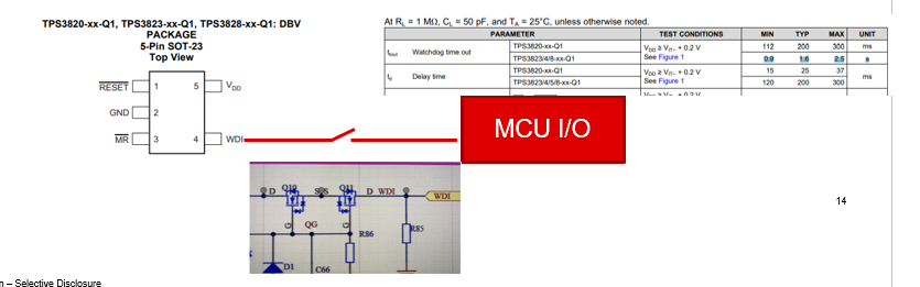
TPS3823-Q1WDI working modes:

  • Use: external I/O
  • Unused:
  • Floating (high impedance): internal timer
  • Place a 1-kΩ resistor from WDI to ground: need BU to explain the working mechanism ( What is the operating mode that is not in high impedance? )

Application description:

  • Customers have special functional requirements when using TPS3823. There is a switch between MCU and WDI for control.
  • It is expected that when the switch is on, the external WDI signal is given. When the switch is off, the external WDI signal is stopped and the internal WDI signal is used.

Support Needs:

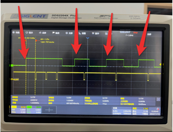
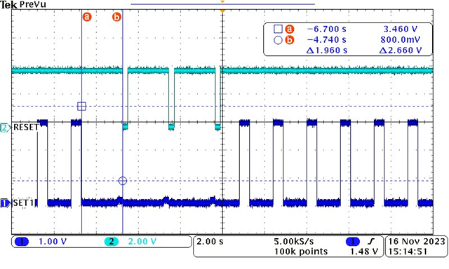
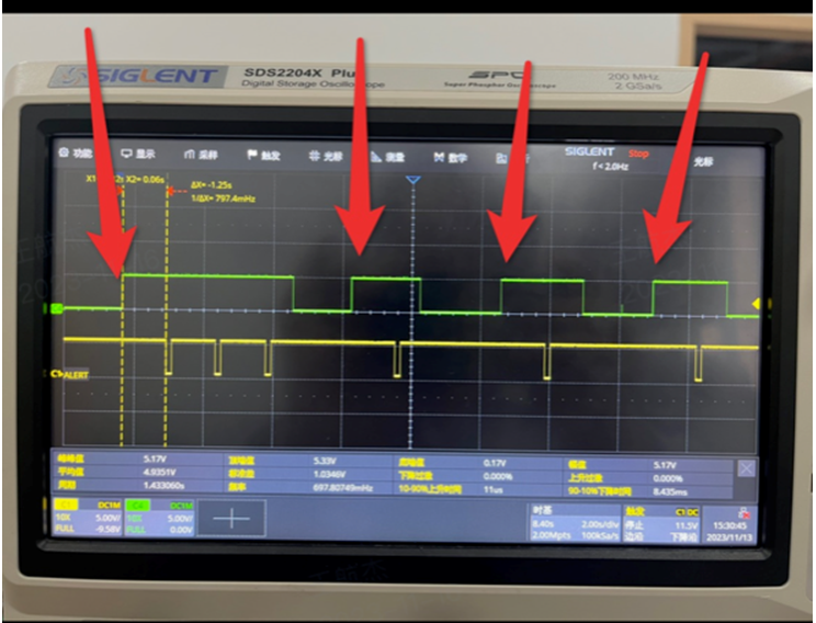
1. Need your help to explain whether the internal timer will start counting from 0 again with a delay when the TPS3823 switches from the high-impedance state to the I/O port.

2. The customer did some tests, closed the switch, switched the WDI from high impedance to I/O( the I/O port did not send a signal ), and found that the time from switch conduction to MCU reset is 180ms~600ms

3. How does the WDI pin determine that it is in a high resistance state?
4. What is the threshold of high resistance state resistance? Or how much more than the resistance value between the WDI foot and the ground will be determined as a high resistance state?

  • Hello,

    1.The watchdog should start counting as soon as WDI is no longer high impedance.

    2. This time is faster than it should be. I can test this in our lab.

    3. When WDI is floating, the internal oscillator provides a pulse through a 40k ohm resistor. When WDI is driven with an I/O, this creates a voltage divider on the WDI pin and the signal from the internal oscillator will become very small and not trigger the watchdog.

    4. We recommend a 1k ohm pull down resistor between WDI and ground to disable the high impedance state.

    Best,

    Walter

  • Hi Walter,

    Thanks for your quick feedback, i still have some confuse for below items:

    1.The watchdog should start counting as soon as WDI is no longer high impedance.

    For example, when the internal counter reaches 10ms, if WDI switches from high impedance to external I/O, how long should the external I/O feed the dog at this time, and whether the internal count of 10ms will be cleared and restarted. count?

    3. When WDI is floating, the internal oscillator provides a pulse through a 40k ohm resistor. When WDI is driven with an I/O, this creates a voltage divider on the WDI pin and the signal from the internal oscillator will become very small and not trigger the watchdog.

    What is the threshold for internal detection?  Why can't measure the waveform of WDI with an oscilloscope (WDI is high impedance, and the equivalent impedance of the oscilloscope is 1M)


  • Hello,

    My apologies I made a mistake in my first response. The watchdog does not start at 0 after leaving high impedance. For example, the internal oscillator sends a pulse every ~1.6s. If WDI is connected to I/O immediately after the internal pulse is sent and the microcontroller does not send a WDI pulse, reset will trigger after 1.6s. If WDI is connected to I/O 1s before the next internal pulse is sent and the microcontroller does not send a WDI pulse, reset will trigger after 600ms. 

    The internal pulse is small but it can be measured with an oscilloscope connected to the WDI pin. Using a 2.2M probe I measured a 2V triangular pulse with a pulse width of ~35us. Input low threshold voltage is 0.3 x Vdd.

    Best,

    Walter

  • Hi Walter,

    Thanks for your update,  there are still differences between the actual tested waveforms and this description.

    The yellow one is the watchdog reset pin waveform, the green one is the WDI signal, the arrow points to the four switching processes from internal WDI to I/O(5V), all four times are 1.25s. Could you please confirm the root cause?

    1. Need your help to explain the working mechanism of the internal circuit when WDI switches from high impedance to I/O. It is best to have simulation and test verification waveforms, thanks.

  • Hi Hangjie,

    After connecting WDI to I/O there is no signal being sent to WDI. This is causing the reset to trigger. A positive or negative transition needs to be sent to WDI every 0.9-2.5s

    Channel 1 is a 1.6s pulse on the WDI pin. Channel 2 is the reset signal. I have a 1k pulldown resistor connected to WDI to keep the pin in low impedance. When I stop sending the WDI pulse reset is triggered.

    Best,

    Walter

  • Hi Walter,

    Since the customer's test results are inconsistent with below description, could you please test and verify it and provide test waveforms? thanks a lot.

    "For example, the internal oscillator sends a pulse every ~1.6s. If WDI is connected to I/O immediately after the internal pulse is sent and the microcontroller does not send a WDI pulse, reset will trigger after 1.6s. If WDI is connected to I/O 1s before the next internal pulse is sent and the microcontroller does not send a WDI pulse, reset will trigger after 600ms. "

    all four times are 1.25s.

  • Hello Hangjie,

    When the customer is connecting WDI to the I/O it does not look like they are sending pulses to the watchdog. This is causing the watchdog to reset after 1.25s. This is within the data sheet range timeout range of 0.9s-2.5s. 1.6s is the typical timeout time that I used for the example.

    Thanks,

    Walter