This thread has been locked.

If you have a related question, please click the "Ask a related question" button in the top right corner. The newly created question will be automatically linked to this question.

LMR38010-Q1: LMR38010-Q1: no feedback network compensation required?

Part Number: LMR38010-Q1
Other Parts Discussed in Thread: LM5164-Q1, , LM5163-Q1, LMR38010

Dear all,

I noticed that LMR38010-Q1 doesn't apparently need any feedback compensation network, such as the one required by its older 'brother' LM5164-Q1.

Please refer to page 11 of LM5164-Q1 datasheet.

Is the TYPE 3 (lowest ripple) network totally useless in case of using LMR38010-Q1, or worse, is it detrimental to LMR38010-Q1 operation?

Best regards

A. L.

  • Hi A.L.

    Thank you for your question. These two devices are not related and only share being buck regulators. That being said, TI does not recommend applying type 3 ripple feedback to a current mode buck such as the LMR38010-Q1. The LMR38010-Q1 also contains internal compensation and adding type 3 compensation might interfere with this device's stability by adding unnecessary poles and zeros. 

    Hope this helps, 

    Joshua Austria

  • Hi Joshua

    Thank you very much for your answer.

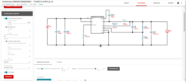
    From Webench platform, I see several things that don't fit with my understanding.

    1) With default configuration (for my use case, of course):
       - LM5163QDDARQ1: Vout,pp=5.5mV
       - LMR38010SQDDARQ1: Vout,pp=15.2mV
       - LMR38010FSQDDARQ1: Vout,pp=1.8mV
       I presumed that LMR30810-Q1 performed better than LM5163-Q1, but probably that is not the case in my scenario. Is that right?

    2) With default configuration, theoretical switching frequency is for both LMR38010-Q1 devices < 500KHz,
       therefore I tried with a 12K resistor on Rt (giving a theoretical switching frequency of 2.1MHz), leaving all things unchanged.
       Vout,pp are:    
       - LMR38010SQDDARQ1: Vout,pp=76.0mV (!!!)
       - LMR38010FSQDDARQ1: Vout,pp=0.9mV
       However, switching frequency is by far different from theoretical one: respectively 42KHz (!!!) and 600KHz.
       How is that possible, and how is the LMR38010SQDDARQ1 performance so bad?

    3) I see that with LMR38010FSQDDARQ1 there is an added capacitor Cff (Feed Forward Capacitor?) that I don't see in the datasheet. Where can I find a reference to this capacitor?
       Moreover, Gain Margin and Phase Margin do appear on the Operating Values of the "FS" version, as opposed to "S" version that appears to be stable under all circumstances
       Messing around with LMR38010FSQDDARQ1 Output Capacitor value, I see that decreasing the capacitance leads to an instable cicuit (???). Phase margin is too low. How is that possible?
       Therefore, I assume that LMR38010SQDDARQ1 and LMR38010FSQDDARQ1 work in a totally different way in my case (0.1A out), but I am not able to find a clear explanation of the way LMR38010FSQDDARQ1 operates in the datasheet, and more specifically how Cin, Cout, Cff Rt and L must be dimensioned. Where can I find additional info?

    4) Both devices seem to be stabilized at 2.1MHz (low Vout,pp with LMR38010SQDDARQ1 and no warnings with LMR38010FSQDDARQ1) with a ton of output capacitance (i.e. >50uF). BUT real frequency is by far lower (respectively 60KHz and 610KHz).
       Leaving that aside, I can not afford to put such a heavy filtering in my circuit. What do you suggest?  

    5) Is a min. Phase Margin of around 30° acceptable (@Vin=5V) ? (LMR38010FSQDDARQ1)


    Best Regards

    A. L.

  • Hi Alessandro,

    Thank you for your questions, I will address them semi-sequentially. 

    1) What is your use case? I can't really determine what is good for your use case but if those values are good with your design then I presume yes.

    2) I was able to get the webench designer to work for both parts. A couple things to note:

    Be advised that the webench designer will automatically limit and shift parameter limits around around based on the inputs you give it. Setting your input to a concise range will allow you to change your frequency on the tab to the right and click "redesign" which should autopopulate the the various components such as the resistors for you. For example, using the default ranges of VIN: 7-80 V with VOUT: 5 V will not allow you to change your switching frequency accurately, and your design may be subject to some frequency foldback as detailed in the datasheet in section 8.3.6. Thus the webench designer will limit frequency and/or not allow resistor changes. Changing the range of VIN to 

    Please be advised as well that the LMR38010S is a non FPWM available part while the LMR38010FS is an FPWM part, so the LMR38010S will automatically change its switching frequency at light loads. 

    3) The feedforward capacitor is a toggle on/off option on the left hand side. It should be available for both designs. See below:

    A feedforward capacitor is a commonly used low value capacitor placed across the top feedback resistor to improve load transient and loop stability characteristics. It does this by adding one zero and one pole to the loop and with proper values can help stabilize a design. You can find more about this from an app note on a different part, but most of the equations should still be relevant and help with calculating a feedforward cap if necessary for your design. 

    I see gain and phase margin on both designs 

    Changing output capacitance will change where your zeros/poles are and can lead to instability. 

    Both devices should operate similarly except that the FS version is FPWM whereas the S version is not. The immense discrepancies in design may have been due to the feed-forward capacitor toggle. The main differences between these devices should be the operating frequency at light loads.

    4) Please see above.

    5) Phase margin of 45 degrees is usually considered minimum, and phase margin of 60 is considered ideal. 

    If you tried all this and would still like more help, please send your webench design and we can try and work through it. 

    Thank you,

    Joshua Austria

  • Dear Joshua,

    let's restart from the basics.

    LMR38010-Q1 datasheet states that modulation frequency can go as high as 2.2MHz.
    In Webench interface, for Vin=5-75V and Vout=3.3V it is only possible to change frequency up to 1.331MHz.
    How is that possible?

    From (3) and (4) equations in the datasheet, LMR38010 should go into frequency foldback mode.
    Don't the devices 1) LMR38010S and 2) LMR38010FS enable frequency foldback by default?

    If we want to have stable switching frequency, we should choose 1) LMR38010FS and 2) Rt which could span from Vin_min to Vin_max without frequency foldback.
    Is the above statement true? 

    Thanks in advance

  • Hi Alessandro,

    Thank you for your questions. 

    The LMR38010-Q1 datasheet does state this. However, in webench, in order to achieve this modulation frequency, you must limit your input/output conditions as the switching frequency of 2.2 MHz is not valid for all loading conditions (i.e. 80 Vin and 5 Vout). As stated above in part 2), there is frequency foldback that limits switching frequency when VIN and VOUT are far apart, as Ton_min and Toff_min limit duty cycle and thereby require lower switching frequencies to properly regulate.

    Yes both devices have frequency foldback. While LMR38010FS is FPWM, this is still subject to frequency foldback for very light loads and switching frequencies above 1.2 MHz. See section 8.3.6 of the datasheet.

  • Hi Joshua

    we will definitely choose the FPWM version of LMR38010-Q1, as we are always under 'light load' conditions (Iout<0.1A), and Vout ripple matters very much to us,
    and moreover, we wouldn't want the frequency to shift under light loads, thereby getting the RF spectre dirty in regions of interest.

    Let me understand this:
    in FPWM, we should have fixed switching frequency,
    given that conditions no.5 and 6. of the LMR38010 datasheet are both verified for the chosen Vout and fsw.
    (Vin_min< Vbatt <Vin_Max).
    Is this right?

    Therefore, with fsw and Vout satisfying equations no.5 and 6.,
    we would never reach frequency foldback, no matter of how 'light' are our loads (also @Iout= 0A).
    This is confirmed by the afore mentioned equations 5 and 6, which do not depend on current.
    Is this right?
    (Hint: in Webench I always get the same switching frequency by varying the load, for FS device, also @Iout=0A)

  • Hi Alessandro,

    Thank you for your questions. Yes, you should not reach frequency foldback if you meet equations 5 and 6. For FPWM the special stipulation is that for switching frequencies above 1.2 MHz and very light loads, frequency foldback can be expected. Please see this excerpt from section 8.3.6 of the datasheet:

    Thank you,

    Joshua Austria