This thread has been locked.

If you have a related question, please click the "Ask a related question" button in the top right corner. The newly created question will be automatically linked to this question.

UCC27201: Boostrap cap

Part Number: UCC27201

Customer found some failure returns from field site after customer product released for some years. The failure part including MOSFET and boostrap cap.

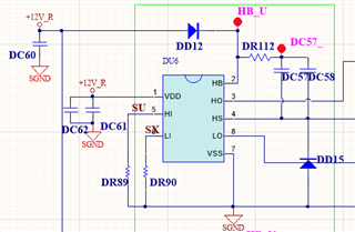
In the schematic, DC57 and DC58 are 22uF Cap, and there is an ex. diode added.

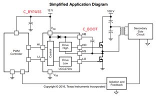
Is there any risk when higher boostrap cap 22uF x2 being used? Please describe it more details and advice. 

Application: e-scooter

DC Bus: 48V

Regards

Brian

  • Hey Brian,

    Thanks for your question regarding the UCC27201.

    A few things about large capacitances such as these as your bootstrap capacitor. The initial start up will be long as it takes a long time to charge these capacitors to begin switching. There is also a large current for this from VDD to HB to charge these capacitors. This current is limited by a bootstrap resistor which it appears that you are doing with DR112. With large bootstrap capacitors, it is important that your bypass capacitors have 10 times more capacitance than the bootstrap capacitors. Therefore, DC60, DC61, and DC62 should have 10 times more capacitance than DC57 and DC58.

    For these capacitor selections, we advise using ceramic X7R capacitors for this as they are cycled at high frequencies. With electrolytic capacitors, they typically do not last as long as the ceramic capacitors do due to being cycled so much.

    One possible way to help these large capacitors to handle these fast transients is to add a small 100nF X7R ceramic capacitor directly at the HB-HS nodes. This will have faster charge up times and handle transients better than the large capacitors.

    Let me know if you have any further questions.

    Thank you,

    William Moore

  • Thanks William,

    Here are some further specific questions to confirm, please clarify them. 

    1. In the datasheet, it says the typical range of HB bypass cap is 0.022uF to 0.1uF. It should not be a limitation when this part is designed since you mentioned that "With large bootstrap capacitors, it is important that your bypass capacitors have 10 times more capacitance than the bootstrap capacitors", is it correct?

    2. Is there any problem with existing customer circuit without any modification? Is that possible to damage the external FET or other components? if so, how does it make?

    It looks It has big problem since existing bypass cap doesn't have 10 times more capacitance than the boostrap cap,, correct?

    3. When DC57 & DC58 is using 22uF for boostrap cap, does it need 0.1uF bypass cap connected in parallel for noise immunity?

    Regards

    Brian

  • Hey Brian,

    1. It seems there may be some differences in terminology that I used versus the datasheet. The HB bypass capacitor that the datasheet is referring to is the bootstrap capacitor from HB to HS. The bypass capacitor that I was referring to is on VDD to GND. This is discussed to some extent at the end of Section 9 - Power Supply Recommendations in the datasheet. In your scenario the bypass capacitors are DC60, DC61, and DC62, depending on which of these is placed close to the IC. In bootstrap circuitry recommendations, the bypass capacitance (VDD-GND) that is located near the IC pins should be at least 10 times greater than that of the bootstrap capacitance (HB-HS). You can reference the Bootstrap Circuitry Selection for Half Bridge Configurations App Note at this LINK.

    2.  With the damage that occurred to the FET and the bootstrap capacitor, it is hard to determine if one could've cause the other or they failed concurrently. If DC57 and DC58 are electrolytic capacitors, that could be the root of the failure as these sometimes wear out over time due to the fast switching cycles experienced in this half-bridge configuration.

    3. By adding the HB-HS capacitor of 100nF, you help with noise immunity and transients experienced during the switching cycle which could help these large capacitors as they are not as well suited for cycling quickly.

    Let me know if you have any further questions.

    Thank you,

    William Moore

  • Very Thanks. Here are further questions.

    1.We understanding how to get the cap value as you bring up above. However, customer wonder to know what's the max. value of the boostrap capacitance on HB-HS pin? 100uF or no limitation? 

    The boostrap cap of 22uF x2 was calculated by the datasheet equation based on specific MOSFET's parameters as below details.

    2. In existing application circuit, the capacitance on VDD-GND is 470uF that is already greater than 10 times of the boostrap cap. however, customer system is 3phase topology which means there are three units of the UCC27201s are being used. is 470uF ok for 3ph topology? Or it needs to have 3 times of the 470uF. 

    Regards

    Brian

    Regards

    Brian

  • Hey Brian,

    1. There is not necessarily a limit as to the how much capacitance you can put on HB-HS for the bootstrap capacitor. With larger capacitances, it takes longer to charge at startup, you need low ESR here as a high ESR will cause voltage drop on the high-side gate and slow down the cycling process of the capacitor, and a larger capacitor will have a lower self resonance frequency which would cause problem at high frequencies because it that is exceeded, then the capacitor begins to act inductive.

    • What frequency are you running at?
    • What duty cycle is this operating at as well?
    • What is the size of your gate resistors as well?
      • I am not so sure that you need as large of bootstrap capacitors unless your operating conditions warrant that. Based on the information given in the table, I am not getting that much required capacitance.
    • Are you driving 3 FETs per side of the UCC27201 and there are 3 drivers, so 18 total FETs?

    2. For the 10 times larger bias capacitor on VDD-GND, that is for a capacitor that is placed close to the IC for that individual driver. So, you would want to place a 10x capacitor at each gate driver and you could also have a capacitor on VDD-GND elsewhere if needed but that doesn't factor into the bias capacitor that the gate driver needs.

    Let me know what you find and if you have any further questions.

    Thank you,

    William Moore

  • Thanks. 

    1. So it likely there is no limitation for boostrap cap which means 44uF (22uF x2) has no violate the spec. 

    2. In the datasheet, it is specified the bypass cap (0.022 to 0.1uF). We're confused that the relationship between bypass cap and boostrap cap? Could you help to point out where the bypass cap need to be placed on PCB?

    Regards

    Brian

  • Hey Brian,

    1. You are correct that this does not violate spec, but large capacitors do not perform as well at the high switching frequencies as well as smaller capacitors do. Lowering this capacitance to a much lower value which would allow for the use of a low ESR, ceramic, surface mount, X7R capacitor as well as allowing for much smaller bypass capacitors on VDD.

    2. I believe that you are referring to the bottom of Section 9 Power Supply Requirements. There are two capacitors needed for a half-bridge gate driver in a typical setup. This can be seen below in the image. The bootstrap capacitor which is located as close to the IC as possible and connected HB to HS. This is a local decoupling capacitor and is for supplying the high side drive current. The other capacitor is the bias capacitor or bypass capacitor which is located as close to the IC as possible and is connected VDD to VSS. This is used for the current pulse for HO that is sourced through the VDD pin. This is used for decoupling and should also be a low ESR, ceramic, surface mount, X7R capacitor. The bypass capacitor is recommended to be at least 10 times greater than the bootstrap capacitor.

    For example, if you were to have a 1uF bootstrap capacitor, you would need at least a 10uF bypass capacitor.

    Let me know if you have any further questions.

    Thank you,

    William Moore