This thread has been locked.

If you have a related question, please click the "Ask a related question" button in the top right corner. The newly created question will be automatically linked to this question.

LM3409HV: LM3409HV

Part Number: LM3409HV
Other Parts Discussed in Thread: TPS92641, , LM3409
Hello Jonard,
 
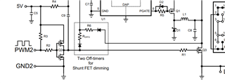
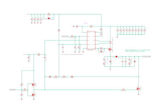
we now have a 11 channel driver with components on both sides.
Please take a look to the pictures and both pdf attached.
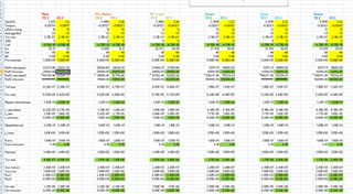
I calculted all parameter with the table attached. Open office table document.
 
The driver all work and even emi tests are good.
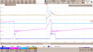
We have the problem that with that low pwm duty cycle the light is not stable and flickers. We had the same experience with the TPS92641.
 
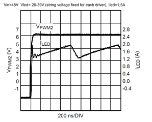
We want stable led current after 100ns but the current peaks change in amplitude and it take 1-2us to reach the stabel region. That's to slow.
We have a 2,7nF parallel to the output. It helps stablizing the current more. Leaving it out does not make anything faster. 
 
What is wrong with this design?
I want to reach the values promized in the demo board user guide.
Any ideas?
 
Best regards
Martin Hermann
  • Old case number is CS1994021. Please send me an email.

  • Hi, Martin,

    I think you've forgot to attach the files, i also can't find any info related to CS1994021. Does it mean another E2E thread ID? Any link for it? 

    May i know what is the application? Why you need to stable led current after 100ns? 

    I don't think it is possible to stable led current within 100ns with a switching mode LED driver. You have to set bandwidth > 10MHz with much higher switching frequency.  

  • Hi Xiaoguang1,

    1. This was my last contact to Jonard Rico:

    -----------------------------------------------------------------------------------------------

    CS1994021: LM3409HV Calculation Tool

    "

    2023-09-29 06:32:56 CDT - Jonard Rico Customer
    Response


    Hello Martin,

    I hope all is well on your end.

    A pleasant day to you and I apologize for this delayed follow-up.

    I have not heard back from you since my last email. It seems like the information I presented to you in my previous email have already resolved your inquiry and you no longer require my assistance moving forward.

    For this time being, I will place this ticket into a "Resolved" status on my end as well.

    However, if you still have further questions or still need further assistance, or still wish to continue our discussions herein, just let me know by simply replying back to this email.

    Please take note that this case will be automatically closed by our system within 5 days of no response. In such an event, and if your inquiry is not yet resolved, please do create a new ticket in the link provided, and we will continue our support from there.

    https://www.ti.com/info/contact-us.html

    Looking forward to your cooperation. 

    Thank you and always stay safe.

    Kind Regards,

    Jonard Rico
    Texas Instruments Customer Support

    "

    -----------------------------------------------------------------------------------------------

    2. Please check this pdf:

    https://www.ti.com/lit/ug/snva390d/snva390d.pdf?ts=1701160491157&ref_url=https%253A%252F%252Fwww.google.com%252F

    Page 12 Figure 9:

    100% current in <<100ns and stable situation after 200ns. This is what we want to achieve.

     =>>>>   How can I send you scope screenshots and schematics?

    Best regards

    Martin Hermann 

  • Martin, 

    You can just click insert -> image/video/file and attach the files. 

    Figure 9 is achieved by external shunt FET. In the schematic, it is Q3 and related PWM control circuit (PWM2/Q2 etc.) 

    You may also refer to  8.3.8 External Parallel FET PWM Dimming in LM3409 datasheet. 

  • I have two off timer and used a TI excel calculation tool for the parameter. With the second off timer I have 180% over current and ringing for 1us. After 1us the I can see the normal current ripple.
    Without the second off timer I have a current ramp starting from 0-400mA in 100ns and to final 1,5A in 3,5us.

    In both cases a rining at the start stops after 0,5-1,0us. This is the critical low level dimming window where we need stable conditions.

    The main problem with the second of timer is that at low dimming levels the current amplitude changes for the first 1-2us because of the off pulse of the switch node appearing before. It's timing is random and the stored engergy in the inductor changes and that creates random flicker in the led and random noise at special dimming levels, different for different pwm frequencies. We work between 100Hz and 30kHz pwm frequency.
    In total the second of timer and the random pulses are not working for a precise led dimming.

    The wires to the led have a lenght of 2*300mm.

    What can we do here?
    How can we create stable conditions staring at 100ns in best case, minimum after 500ns?
    We can even use a second pwm which creates a pulse before the main signal but creating the 1us ringing in the current does not work for us.

  • Hi, Martin, 

    I'm trying to read the schematic while it looks vague. 

    Some comments:

    1. Remove C56 and connect EN to 5V or Vin always. 

    2, For the tested waveform, what is C1 - switch NC? Can you also monitor T33 gate voltage,inductor current and Coff PIN voltage? 

    3. Toff2 is much longer than Toff1 in this design and it will discharge inductor current continously during PWM off with slower switching frequency. You may set R23 lower value (like 6k) to get lower inductor ripple.   

  • Hello Jonard, 

    C56 is C9 in the above evaluation kit schematic with two off timers. PDF SNVA390D. C56=C9=2,2nF. The EN pin creates a reset and the cycle has a synchronized start. C1 is the switch node with 180% over current and 1us until the current has leveled off.

    I even used the Excel spreadsheet to calculate. I can send it to you, but you have to email me. Uploading files doesn't seem to work here.

    I will carry out tests and measurements 1 - 3 and let you know the results.

    The driver must work for PWM frequencies from 80 Hz to 30,000 Hz. For higher frequencies, a very fast switch-on time is crucial. 100 ns to stable current would be perfect.

    Best regards
    Martin

  • I would like to see this waveform for the led current.

  • Hi, Martin, 

    I will send you email and let us discuss it via email. Thanks!