This thread has been locked.

If you have a related question, please click the "Ask a related question" button in the top right corner. The newly created question will be automatically linked to this question.

TPS7H4003-SEP: Design Calculator mods for parallel operation

Part Number: TPS7H4003-SEP
Other Parts Discussed in Thread: TPS7H4001-SP

When using the design calculator for the TPS7H4003-SEP in parallel mode, what is the correct procedure?

For instance, if the total load is 20A and a dual configuration is being used, I'd assume the following:

1. Enter the VIn, Vout, Kind and "10A" as the load current as if the design were for a single phase

2. Enter delta-Iout at 1/2 the expected load step (5A for example given a total 10A load step for the parallel circuit)

3. Enter the chosen output capacitance suggested based on cells D58, D59 as if it were 1-phase. The actual populated output capacitance will be 2X this value.

4. The Rcomp calculated value will be 4X (n^2) the value needed for the primary converter compensation, divide the calculated value by 4 and use this for Rcomp (see eqn 37 from the datasheet)

5. Ccomp & Chf calculated values are the correct values to populate in the parallel configuration, no changes? (or should these be doubled based on the output capacitance entered at 1/2 the "real" value?)

Is that correct? Are there any other adjustments required (such as modifying the slope compensation?)

Can we update the spreadsheet to include an "N" factor to accommodate the number of phases?

Thanks,

Steve

  • Hey Steve,

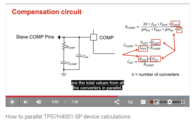
    We have a video on this:
    https://www.ti.com/video/series/t-60-video-series.html

    (See How to parallel TPS7H4001-SP device calculations)

    I will quickly answer your questions:

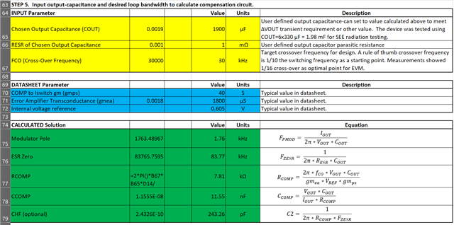
    All you have to do to get a majority of the correct values is go down to datasheet parameters and multiply the COMP to Iswitch gm and Error Amplifier Transconductance by n.

    1. You would use the full current of 20 A

    2. You would enter the full load step delta

    3. You would obtain the full capacitance value

    4. RCOMP would be the correct value

    5. CCOMP and CHF would be the correct value

    The EN resistors would be a bit more complicated.

    The SS would be multiplied by n.

    Your feedback about the change is noted for the next update.

    Thanks,
    Daniel

  • Thanks Daniel - I'll enter the total load currents and total output cap.

    Would you confirm that the inductor value suggested in the spreadsheet is really 1/2 of the 2 populated inductor's values when doing it this way? How is the slope comp resistor calculation impacted (if at all?)

    The spreadsheet calculates Ccomp and Chf according to the video but it doesn't seem to include the "N^2" divider factor in Rcomp

    In this case we see Ccomp & Chf formulas matching the video but not the Rcomp, it doesn't include the /n^2 divider...

    Should I reduce the calculated Rcomp value by 4 when using 2 converters?

    Thanks,


    Steve

  • Hey Steve,

    The inductor value would be incorrect and has to be found per converter.
    The basic calculator with all of the values divided by n would work to find just that value
    IOUT being half of total IOUT ect.

    The n from the video comes from gmea and gmps.
    I find it easier to multiple gmea and gmps in the calculator by n and then the equations come out correctly.

    Note that since COUT is the total COUT you end up dividing RCOMP by 2 not 4.
    The capacitors get scaled in a similar way, by 2 not 4.

    Thanks,
    Daniel

  • Daniel - just verifying, would the comp caps be divided by 2 or multiplied by 2

  • Hey Steve,

    They should be divided by two.
    The extra gain in the circuit from multiple error amplifiers ect. need a lower gain overall.

    Thanks,
    Daniel