This thread has been locked.

If you have a related question, please click the "Ask a related question" button in the top right corner. The newly created question will be automatically linked to this question.

TPS40200-HT: Low Input Voltage Not Working

Part Number: TPS40200-HT
Other Parts Discussed in Thread: TPS40200

Hello,

I have used successfully TPS40200-HT for input voltages higher than 15V.

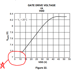
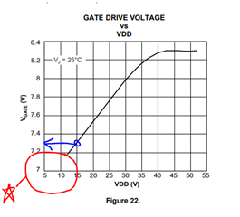
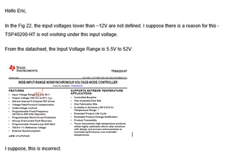
I have problems with the TPS40200-HT for input voltages lower than 15V. I want to use a 6V input for a 3.3V AND 1.8V outputs.  In the specs the minimum input voltage is 5.5V and the minimum output voltage is 700mA.

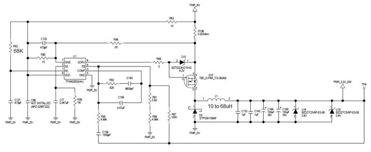
I am trying to use RRC = 68K and CRC = 470pF for a frequency of ~298KHz. I have tried L1 inductors with values of 10uH and 68uH.

Is it something in particular that has to be changed for low input voltages?

Thanks,

Marius Raducanu

  • Hello Marius

    I've tried to find the gate driver voltage VS. VDD data at the low input voltage but I couldn't find because the device is old. 

    If you can, please check the P-MOSFET gate driver voltage on the bench at 6V. 

    -EL  

  • Hello Eric,

    Thanks for answering my question.

    My schematic with a 45V input has a 12V Zener that limits the Source-Gate voltage to 12V.

    When the input voltage is less than ~14V, the Gate voltage drops to ~4V - I suppose this is the problem.

    For the new schematic with a desired 6V input, I have removed the Zener diode between Source and Gate - not required if the voltage is lower than 20V.

    I also disabled the current protection connecting pins 7 and 8 (VDD-ISNS) - to be sure the noise does not affect the output.

    Regards,

    Marius

  • Hello Marius 

    Based on Fig22, the gate output should be ~ 7.3V when VDD=15V. Please check if any excessive voltage drop from the input power supply to the VDD pin. 

    -EL

  • Hello Eric,

    Below is a screen capture of the gate voltage at ~14V input.

    NOTE: These are voltages referenced to GND NOT Source.

    This is a screen capture of the gate voltage with a 13V input:

    Regards,

    Marius

  • Hello Marius

    Something wrong. The voltage drop from VDD to the GDRV should be greater than 6V(at worst case).  

    -EL

  • Hello Eric,

    I added a NOTE in my previous response. The Gate voltages in the screenshot for 14V input are measured referenced to GND - this is a P-Type MOSFET.

    14V (input) - 8V(minim voltage in SS) = 6V (VGATE = (VDD – VGDRV), for 12 < VDD < 52)

    You are using the data sheet of TPS40200. My part number is TPS40200-HT. They are similar but for instance the Table 6.5 is not in the TPS40200-HT data sheet.

    Regards,

    Marius

  • Hello Marius 

    I was referring this waveform.  AS you can see, the voltage drop from VDD to the GDRV is only 4.97V now. It should be greater than 6V (unless the temperature is >125C) 

    -EL

  • Hello Eric,

    The voltage in the screen shot is the gate voltage. The ~4.97V is the delta of the Gate voltage.

    The voltage input for the screen shot above is a little bit more than 14V. The Vgate = 14-8 = 6V. Note that the Voltage input is ~+1V more than the max gate voltage.

    At 14V input, the converter works. If the input voltage is lower than 14V, the gate voltage (GND reference) drops to 4.0V and the converter stops working.

    This is the high temperature version (210C) of the TSP40200 and could be different than the low temperature version. I have ordered lower temperature version (175C and 125C) to test.

    Note that the HT works in a range of 5.5V-52V vs 4.5V-52V.

    Regards,

    Marius

  • Hello Marius 

    The high-side P-MOSFET will be fully on and VOUT will become equal to VIN if the V(GDRV-GND) drops to 4V when V(VDD-GND) is 14V. Please double check if this is what you are observing. 

    -EL 

  • Hello Eric,

    This is the gate voltage when the input voltage is 12V:

    This is the voltage after the MOSFET (Drain):

    The output voltage (after capacitors) is ~0V.

    I agree, when the gate voltage is 4V and the input voltage is 12V, the MOSFET has to be open.

    The testing setup is a PCB used in a schematic for a 45V input and 5.0V output. The P-Type MOSFET is NP50P06KDG-E1-AY. This MOSFET has a relative big Gate charge and capacitance but we have used other MOSFETs with the same result (even worse). The output has 5.0V zener diodes to protect for over voltages. I have used a 150mA load at 14V.

    I have ordered different MOSFETs and waiting to receive them for testing.

    Regards,

    Marius


  • Hello Eric,

    This is the gate voltage with a 16.5V input, 210mA load:

    This is the gate voltage with a 14.6V input, 250mA load:

    The problem appears when the minimum gate voltage is less than 8V.

    In the datasheet the GDRV is limited to VIN-8V:

    Maybe here there is a problem in the Converter.

    Regards,

    Marius

  • Hello Marius.

    1. I agree, when the gate voltage is 4V and the input voltage is 12V, the MOSFET has to be open.==> PMOS should turn on when the input is 12V and the gate to ground voltage is 4V. 

    2. This is wrong. gate-to-ground voltage should swing between ~12V and ~ 6V when he input power supply voltage is 12V. 

    -EL

  • Hello Eric,

    Yes, the gate voltage is wrong for 12V input but why and how can I fix this?

    My only option left is to start testing different MOSFETs and the 175C rated TSP40200.

    Regards,

    Marius

  • Hello Eric,

    Can you comment my previous part of the response:

    In the datasheet the GDRV is limited to VIN-8V:

    Maybe here there is a problem in the Converter.

    For 12V input (VIN), the GDRV is 12V-8V = 4V, exactly what I get in my tests!!!

    Regards,

    Marius

  • Hello Marius.

    This gate-to-ground voltage is correct. I guess your measurement was wrong.   

    -EL

  • Hello Eric,

    What measurement are you referring too?

    Regards,

    Marius

  • Hello Marius

    For 12V input (VIN), the GDRV is 12V-8V = 4V, exactly what I get in my tests==> No, it is not, 16V minus 10V equals 6V. 

    -EL

  • Hello Marius.

    This gate-to-ground voltage measurement is correct.   

    This gate-to-ground voltage measurement is wrong.   

    -EL

  • Hello Eric,

    You are looking to the wrong screenshot.

    This is the gate voltage for 16.5V voltage input that works:

    This is the gate voltage for 12V that does not work:

    It has a maximum of 4.5V.

    "For 12V input (VIN), the GDRV is 12V-8V = 4V, exactly what I get in my tests!!!"

    Regards,

    Marius

  • Hello Eric,

    Please, comment my previous response:

    "In the datasheet the GDRV is limited to VIN-8V:

    Maybe here there is a problem in the Converter.

    For 12V input (VIN), the GDRV is 12V-8V = 4V, exactly what I get in my tests!!!"

    Regards,

    Marius

  • Hello Marius.

    Yes, obviously the driver output voltage is not right.

    Something wrong if this waveform is V(GDRV-GND) when VIN =12V. If this is true, please replace the device and retest. 

    -EL

  • Hello Eric,

    I am getting the same test results for more than one device.

    The datasheet specifies that GDRV = VIN - 8V. Based on this, the VIN cannot be lower than 8V+6V=14V, matching my test results.

    If this is true, the 5.5V minimum input voltage specified in the datasheet is incorrect.

    Regards,

    Marius

  • Hello Marius.

    I am sorry I accidently deleted your post when modifying my response, but there is the copy. The device should work down to 5.5V. Please capture the gate voltage waveforms from 12V down to 6V at 1V step for me. 

    -EL

  • Hello Eric,

    I have a problem in measuring the circuit.

    When it stops working the power is turned OFF.

    I have to modify the circuit to prevent this.

    I will do t6he measurements ASAP.

    Regards,

    Marius

  • Hello Marius 

    Please post the test results when they are ready. Especially, I'd like to see when V(GDRV-GND) in high-logic state @ VIN=12V becomes ~ 4.5V.

    -EL

  • Hello Eric,

    I found the problem.

    The test circuit for TSP40200 that I am using is part of a BIG board that has a switch using two MOSFETs, calculated to work at 42V.

    When I decreased the power, the switch started turning OFF the voltage of the testing circuit at 14V. Unfortunately, I have not measured the input voltage in the TSP40200 circuit to realize this. I have considered the input voltage that I read on the power supply.

    After I shorted the switch, the TSP40200 started working at 6.0V input.

    Here is the Gate Voltage for a 6.0V input, 5V output:

    Thanks for your help.

    Regards,

    Marius

  • Hello Marius 

    Good to hear you resolved the issue. The 6V  test result looks good to me. 

    Thanks for choosing TI. Please feel free to contact us if you have any question.
    -EL