- Ask a related questionWhat is a related question?A related question is a question created from another question. When the related question is created, it will be automatically linked to the original question.
This thread has been locked.
If you have a related question, please click the "Ask a related question" button in the top right corner. The newly created question will be automatically linked to this question.
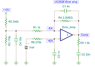
Hi team, I'm facing some difficulty trying to understand this circuit. It involves an error amplifier from UC2526. I want to evaluate its transfer function. However, as stated in the UC2526's datasheet, this is an Operational Transconductance Amplifier (OTA). I've read some explanations about this type of amplifier, but I'm still unsure how to work with it. Can you help me?

Lucas,
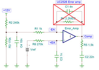
The output of the OTA is a current as opposed to the output of a traditional OA which is a voltage. The image you've attached shows C1 and R4 providing negative feedback such as what we use to adjust gain and frequency response when compensating a traditional voltage op amp. For an OTA (also commonly called a trasconductance amp or gm amp), there is no output-to-input feedback because the gain and frequency response are adjusted by R5 and C2 as you have shown in your schematic. Remove C1 and R4 and you are good to go.
For a traditional voltage OA, the feedback to input impedance ratio determine the closed loop DC gain. For an OTA, the large signal gain is also adjusted and determined by external components around the amplifier but since there is no feedback, the gain is relying upon the OTA transconductance

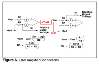
Figure 6 of the UC2526 data sheet shows the connections for sensing/regulating either a positive or negative voltage and I've drawn in red to show how the compensation would be connected for the OTA. For a more thorough explanation, refer to Demystifying Type II and Type III Compensators Using OpAmp and OTA for DC/DC Converters.

Regards,
Steve
Hi Steven,
Thank you for the explanation and the reference for compensators using OTA.
How can I know the gm parameter of the error amplifier in the UC2526?
Do you have any other reference on how to perform OTA analysis? I really want to know how negative feedback would behave.
Best regards.
Lucas,
Error amp gain vs freq given in the data sheet as shown in the graph below. The equivalent transconductance is in the range of 1.1<gm<1.5 but this is not published in the TI data sheet. With the open loop gain and gm transconductance, you should have all you need to compensate the control loop.
Steve
Is it possible to use a external operational amplifier and feed the Comp pin directly with this external compensator? Unfortunately it appears that this datasheet lacks information.
I don't usually design with OTAs but below are some suggestions from previous E2E threads. What about the UC2526 is attractive to you? Because of it's age, it is not well supported as evidence by the lack of EVM/Models/App Notes. Perhaps a better supported, more recent PWM controller would be better?
Steve
Hello Steve,
Which PWM controller would you suggest for replacement? (no need for pin to pin compatible)
Best regards,
Lucas
Lucas,
which PWM controller, depends on your design requirements? You can start here and then parametrically search according to your requirements.
Steve