This thread has been locked.

If you have a related question, please click the "Ask a related question" button in the top right corner. The newly created question will be automatically linked to this question.

UC2526: I am not getting proper Control PWM Signal when output voltage feedback is connected to th UC2526

Part Number: UC2526

Dear SIr,

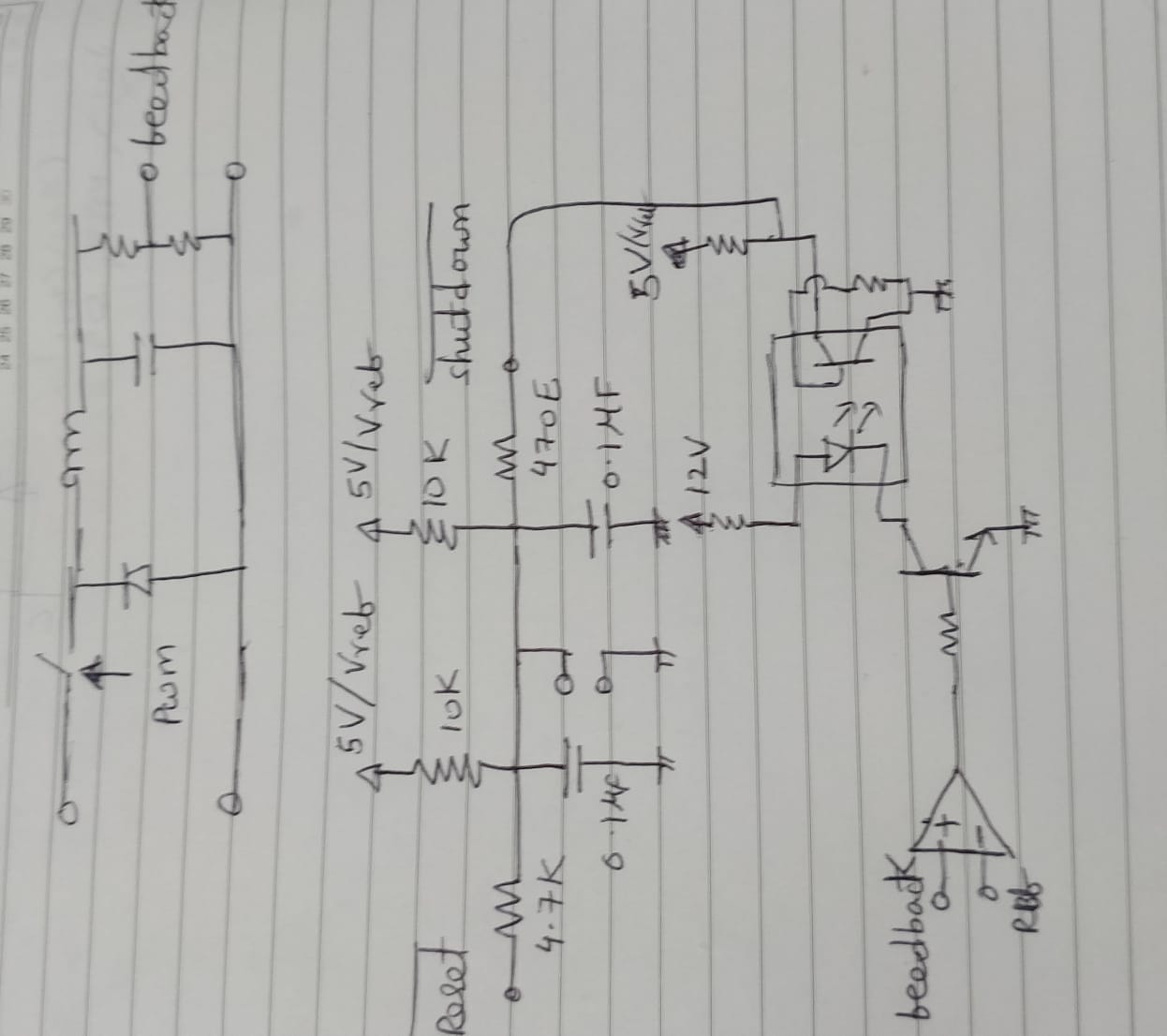
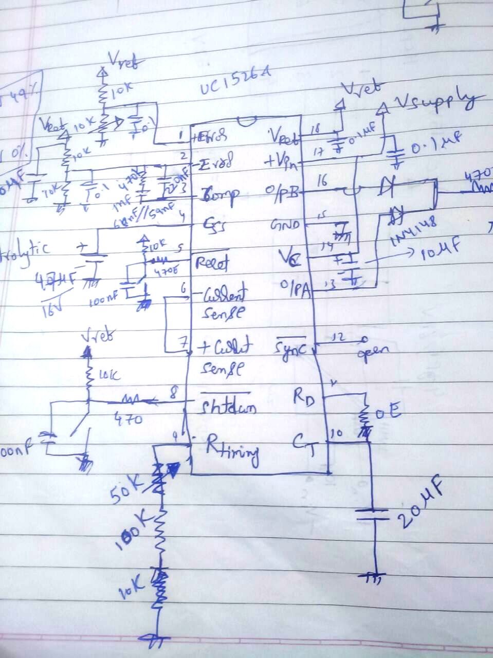
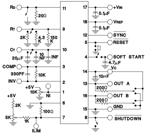
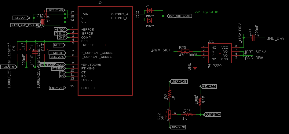
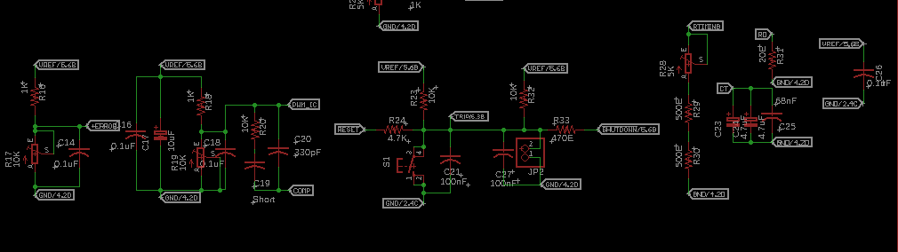
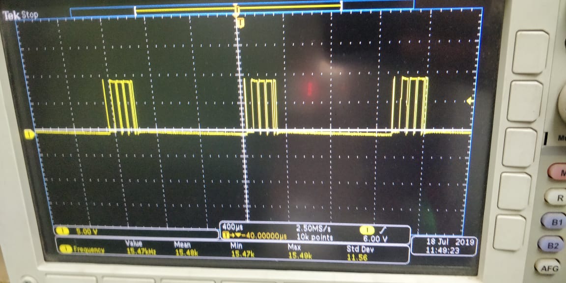
I am not getting proper Control PWM Signal in this arrangement.it is controling output volatge of Buck Converter. But getting good output volatge regulation.I have Shorted Shutdown and reset pin through a resistor. i am controling shutdown pin using transistor and Comparator.i am getting distorted PWM.i have shorted second and third pin of UC2526ADW.

  • Hello 

    • What do you mean by proper control signal ?
    • Pin 11 requires a resistor to GND.
      Your sketch shows  a short from pin 11 to pin 10.
    • Use the open loop test setup shown below :

    Regards

    John

  • Hi Jhon,

    PWM Signal from the UC2526 is not getting proper.when output Voltage of DC to DC Conveter is Regulating.Pwm Signal not seems good.Should i need to add any extra component apart from this.(like Compensation.Here  I am ataching waveform and schematic.

  • Hi Anand,

    I really cant tell from your schematic why you are not getting a fixed pwm signal.

    To help troubleshoot the circuit you could disconnect the diodes on OUTPUT_A and OUTPUT_B.
    Then disable the current limit input pins 6 and 7.

    Review how you have connected the inputs to the error amplifier (pins 1,2 ,3)
    Is this the same as the open loop teest schematic I attached ?

    Regards

    John

  • Hi Jhon

    We assembled a different board with same schematic and layout. Those are working fine.

    What are the reasons we may expect for these improper PWM from UC2526.I tried by changing IC's But  no Improvement.

    Please let us know. you find any reason. what are the pins of UC2526 which are majorly responsible for the PWM.

  • Hi Anand,

    If you built another board and the results are fine then I would look to see what is different in the bad board.

    There must be something miswired or open circuited.

    It is best to carefully document your circuit and test results. If you are just testing a breadboard it is perhaps wise to do a pcb layout design before you proceed
    any further.

    Regards

    John