This thread has been locked.

If you have a related question, please click the "Ask a related question" button in the top right corner. The newly created question will be automatically linked to this question.

TUSB1046EVM: TPS65982 FW config?

Part Number: TUSB1046EVM
Other Parts Discussed in Thread: TPS65982, , TPS65987DDK, TPS65987D, TPS65987

HI,

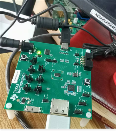
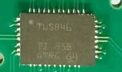
   We had bought on TUSB1046 EVM from a distributor of China.

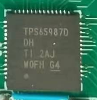
we will use this board to support "DP to USB-C" application.  For our requirement, we also need the PD support. Since on TUSB1046 EVM, there  had the PD chip of TPS65982.

Can we use TPS65982 FW to check the "DP ALT flow" and "PD flow“?

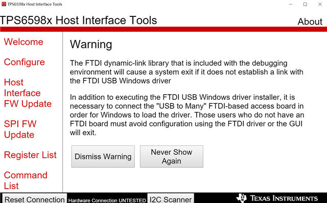
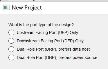
I had download  the "TPS6598X Configuration Tool" and "the TPS6598X Utilities Tool", and we can use the two tools to access TPS65982 to check the "DP ALT flow" and "PD flow“, right?

If I am not right? How can I check the "DP ALT flow" and "PD flow“ with TUSB1046 EVM?

Have a good weekend! Thanks

Haidong

  • Hi Haidong, 

    Can you elaborate what do you mean by "DP Alt Flow" and "PD Flow"? To check the PD messages when a connection is made you'll need a PD analyzer/sniffer to decode the CC communication. You can also use the GUI to check the live status reading of the TPS65982 by entering 'Debug mode' or by using an external I2C host (i.e. Aardvark adapter) to read into specific register(s). 

    Thanks and Regards,

    Raymond Lin

  • Hi, Raymond

         My wording confused your understanding, Sorry. 

         Actually, we just want to check the "PD messages" or "DP ALT messages" when a connection is made.

         And I want to confirm two questions:

    1. Can you recommend a PD analyzer/sniffer?

    2. I can use the GUI to check the live status reading of the TPS65982 by entering 'Debug mode'.  Can you send me the downloading address of "the GUI"?

    I want to check if I had downloaded the right one. 

    Thanks.

    Have a good weekend!

    Haidong

  • Hi, Raymond

       I had got the TUSB1046 EVM. 

    You meaned I can use the GUI to check the live status reading of the TPS65982 by entering 'Debug mode'.  And we had no an external I2C host (i.e. Aardvark adapter) now.

    Two questions: 

    1. How can I enter 'Debug mode'?

    2. How are PC (or USB IF) and TUSB1046EVM connected?

    Thanks

    Haidong

  • Hi, Raymond

        I had tested DP ALT mode with TUSB1046 EVM. I seemed not working.

        DP IF input (PC)------> TUSB1046EVM------> Tpye-C fully cable------>Tpye-C display with 5V power in.

         From PC side, It can detect “the second display”, but not active.  And there is no any display on the monitor.

        Also, I do the following test.

        DP IF input (PC) & USB3.0 host inpu------> TUSB1046EVM------> Tpye-C fully cable------>Tpye-C display without external 5V power

    in. From PC side, It cannot detect "the second display".

       Before I do the upper test. I also do the test with "DP IF input (PC)------> DP to Tpye-C cable------>Tpye-C display".  The testing works normally.

        Can you help me analyze the reason? Thanks

    Haidong

  • Hi, Raymond

        When I did the test of " DP IF input (PC)------> TUSB1046EVM------> Tpye-C fully cable------>Tpye-C display with 5V power in."    

        I tested CTL0, CTL1 & FLIP, CTL0= High(3.3V),CTL1= Low(0V), FLIP=LOW (When I changed the Orientation of TYPEC, It will be high)

       The PD chip is TPS65987DHD,  The version of TUSB1046EVM is "INT053 Rev F";

    Best Regards

    Thanks

  • Hi Haidong, 

    1. Can you recommend a PD analyzer/sniffer?

    We recommend similar devices such as the Total Phase PD Analyzer (https://www.totalphase.com/usb-power-delivery-analyzer/), this device is no longer in production but anything similar should work. 

    2. I can use the GUI to check the live status reading of the TPS65982 by entering 'Debug mode'.  Can you send me the downloading address of "the GUI"?

    You can find the download link to the GUI here: https://www.ti.com/tool/download/TPS6598X-CONFIG 

      I had tested DP ALT mode with TUSB1046 EVM. I seemed not working.

        DP IF input (PC)------> TUSB1046EVM------> Tpye-C fully cable------>Tpye-C display with 5V power in.

         From PC side, It can detect “the second display”, but not active.  And there is no any display on the monitor.

        Also, I do the following test.

        DP IF input (PC) & USB3.0 host inpu------> TUSB1046EVM------> Tpye-C fully cable------>Tpye-C display without external 5V power

    in. From PC side, It cannot detect "the second display".

       Before I do the upper test. I also do the test with "DP IF input (PC)------> DP to Tpye-C cable------>Tpye-C display".  The testing works normally.

    Based on your description, it seems like the PD was able to negotiate a successful power contract and enter Alternate Mode -> Display Port. This seems like something on the TUSB end, I'll forward this thread to the proper team for additional support. 

    One note to make, TPS65982 is an older Power Delivery Controller, we do not recommend using this device for new designs as it is outdated in terms of the firmware and GUI configuration. For new designs, please refer to TPS65987DDK. 

    Thanks and Regards,

    Raymond Lin

  • Haidong

    Can you please send me a picture of the EVM so I can check its configuration?

    Another PD analyzer is Ellisys Type-c tracker, https://www.ellisys.com/products/ctr1/. It can decode both PD and DP protocol.

    When testing TUSB1046EVM, is it DisplayPort only? If this is the case, are you supply an external power to the EVM?

    Thanks

    David 

  • Hi,David

       Please refer to the picture.


    Yes,I do the test with “DisplayPort only”. And  there was an external 5V power to the EVM.

        I had tested DP ALT mode with TUSB1046 EVM. I seemed not working.

        DP IF input (PC)------> TUSB1046EVM (with  external5V power in)------> Tpye-C fully cable------>Tpye-C Monitor .

         From PC side, It can detect “the second display”, but not active.  And there is no any display on the monitor.

     I tested CTL0, CTL1 & FLIP,The result are:  CTL0= High(3.3V),CTL1= Low(0V), FLIP=LOW (When I changed the Orientation of TYPEC, It will be high). It seems work in USB 3.1 ONLY.

    Also, I had downloaded the GUI from: https://www.ti.com/tool/download/TPS6598X-CONFIG ;

    How can I connected PC (installed GUI) and TUSB1046EVM? That is, What's the device (or cable) between PC &  TUSB1046EVM? 

    Thanks

    Haidong

  • Haidong

    The PC should have a standard DP connector, so the connection between the PC and TUSB1046EVM will be a standard DP cable. 

    But if CTL0=3.3V, and CTL1 = 0V, then you are in USB3.1 mode as you said, and not in DP Alt Mode. So the Type-C negotiation does not work. 

    I looked at the jumper setting and it looked correct. Do you have another Type-C monitor you can try?

    Thanks

    David

  • Hi,David

        I confirmed the standard DP connector were used with PC.

        Also  I confirmed “CTL0=H”. 

       This morning. I chaned another Type-C monitor. The result was same as before.

        The TUSB1046EVM board version is “INT053 Rev F”. 

    PD IC is "TPS65987D"  .  

    And The TUSB1046 is as the following picture. 

    And I requested schematic of TUSB1046EVM. And I got one with the version "TUSB1046 - INT053A USB-C(TM) Enabler Board REVA2”

    In the schematic, the PD IC is still TPS65982. Can you send us the right version of the schematic ?

    Aslo I doubted that the FW version does not matched with the TUSB1046 EVB in my hand. How can I check?

    At last, I had downloaded the GUI from: https://www.ti.com/tool/download/TPS6598X-CONFIG ;

    How can I connected PC (installed GUI) and TUSB1046EVM? That is, What's the device (or cable) between PC &  TUSB1046EVM? 

    Thanks

    Haidong


  • Haidong

    The cable between the PC and TUSB1064EVM will be a standard passive DP cable.

    Please see attached for the EVM schematic. 

    INT053F-001_Schematic.pdf

    Looking at the schematic, can you move the R13 0 ohem resistor to R11? 

    Can you also pull JMP10 high as well?

    Thanks

    David

  • HI, David.

          1. I moved the R13 0 ohem resistor to R11. 

           2.  You said "Can you also pull JMP10 high as well?" Maybe there is a typo.  I made JMP9 (HPDIN)=3.3V ;

           3. Connected CTL0 to GND, CTL1 to 3p3_VCC.

    1&2, DP ALT not work;

    1&3, DP ALT not work

    1&2&3 DP ALT work, the TYPE-C monitor can display well.

    May the FW version of TPS 65987 is not right.  Can you send us the right version of FW ?

    And how can I downloaded the FW ?

     Also, I had downloaded the GUI from: https://www.ti.com/tool/download/TPS6598X-CONFIG ;

    How can I connected PC (installed GUI) and TUSB1046EVM? That is, What's the device (or cable) between PC &  TUSB1046EVM? 

    Thanks

    Haidong

  • HI, David.

          1. I moved the R13 0 ohem resistor to R11. 

           2.  You said "Can you also pull JMP10 high as well?" Maybe there is a typo.  I made JMP9 (HPDIN)=3.3V ;

           3. Connected CTL0 to GND, CTL1 to 3p3_VCC.

    1&2, DP ALT not work;

    1&3, DP ALT not work

    1&2&3 DP ALT work, the TYPE-C monitor can display well.

    May the FW version of TPS 65987 is not right.  Can you send us the right version of FW ?

    And how can I downloaded the FW ?

     Also, I had downloaded the GUI from: https://www.ti.com/tool/download/TPS6598X-CONFIG ;

    How can I connected PC (installed GUI) and TUSB1046EVM? That is, What's the device (or cable) between PC &  TUSB1046EVM? 

    Thanks

    Haidong

  • HI, David.

          1. I moved the R13 0 ohem resistor to R11. 

           2.  You said "Can you also pull JMP10 high as well?" Maybe there is a typo.  I made JMP9 (HPDIN)=3.3V ;

           3. Connected CTL0 to GND, CTL1 to 3p3_VCC.

    1&2, DP ALT not work;

    1&3, DP ALT not work

    1&2&3 DP ALT work, the TYPE-C monitor can display well.

    May the FW version of TPS 65987 is not right.  Can you send us the right version of FW ?

    And how can I downloaded the FW ?

     Also, I had downloaded the GUI from: https://www.ti.com/tool/download/TPS6598X-CONFIG ;

    How can I connected PC (installed GUI) and TUSB1046EVM? That is, What's the device (or cable) between PC &  TUSB1046EVM? 

    Thanks

    Haidong

  • HI, David.

          1. I moved the R13 0 ohem resistor to R11. 

           2.  You said "Can you also pull JMP10 high as well?" Maybe there is a typo.  I made JMP9 (HPDIN)=3.3V ;

           3. Connected CTL0 to GND, CTL1 to 3p3_VCC.

    1&2, DP ALT not work;

    1&3, DP ALT not work

    1&2&3 DP ALT work, the TYPE-C monitor can display well.

    May the FW version of TPS 65987 is not right.  Can you send us the right version of FW ?

    And how can I downloaded the FW ?

     Also, I had downloaded the GUI from: https://www.ti.com/tool/download/TPS6598X-CONFIG ;

    How can I connected PC (installed GUI) and TUSB1046EVM? That is, What's the device (or cable) between PC &  TUSB1046EVM? 

    Thanks

    Haidong

  • Haidong

    Please see attached binary file for 

    INT053D_Firmware.zip

    For firmware update, please see this app note, https://www.ti.com/lit/an/slvae21a/slvae21a.pdf

    Thanks

    David

  • Hi, David

         I had downloaded FW & the app note.

     I also confused the following. 

    1. What's the tools used in PC?

    2. How do I setup the connetion between PC and TUSB1046EVM (Or, what's the generic tools used in the connection?)

    3. How do I operate SW in PC (and setup TUSB1046EVM) step by step?     

    Can you give us the user guide with step by step?

    For PD IC (TPS65987)

    We will use it to service TYPE-C inferface for all the three functions (Modes). A. DP ALT; B. Power Delivery (PD3.0); C. USB 3.1;

      Can the TPS65987 change the modes automatically?

    At last, when we complete the evaluation of TUSB1046EVM. We will do our design with TPS65987&TUSB1046. So we also need the source codes of the FW of TPS65987. Can you offer us? Thanks!
    Haidong

  • Hi, David 

        Actually,I am very confused.

            For TUSB1046, HDPIN and CTL1 are actually in one PIN. CTL1="H", Actually, HPDIN is "H".

    Then I checked JMP9 . 

           In the schematic, R37 should be mounted and R36 should be not mounted.

    But in the TUSB1046EVM, R37 was not be mounted, and R36 was mounted.

    That is, when I set JUM9(DCI_CLK/HPDIN)=3.3V, actually set DCI_CLK=3.3V. And DP ALT works.

    But if I did not set  DCI_CLK=3.3V. DP ALT does not work.

    Why?

    What's the right setting?

    Haidong

  • Hi Haidong, 

    1. What's the tools used in PC?

    The Application Customization Tool for TPS6598x series allow the user to easily generate a configuration for the PD controller based on the system requirements. Once a configuration is complete, user can either use the GUI directly to flash the EEPROM (if available) or generate a binary image of the low region and the full flash. 

    2. How do I setup the connetion between PC and TUSB1046EVM (Or, what's the generic tools used in the connection?)

    If you want to re-flash the on-board PD controller (TPS65982) on the TUSB1046EVM you can use an Aardvark adapter to directly flash the SPI memory. You can refer to this tutorial training series on using the GUI to flash: https://www.ti.com/video/6122862051001 

    For PD IC (TPS65987)

    We will use it to service TYPE-C inferface for all the three functions (Modes). A. DP ALT; B. Power Delivery (PD3.0); C. USB 3.1;

      Can the TPS65987 change the modes automatically?

    TPS65987 will automatically communicate with the connected far-end device to determine the Power Delivery requirements follow by any USB data or DisplayPort enumeration. You will need to configure the PD to be able to detect USB3.1 and DP Alternate Mode through the GUI, more details on how to set it up here: https://www.ti.com/lit/pdf/slvae16 

    At last, when we complete the evaluation of TUSB1046EVM. We will do our design with TPS65987&TUSB1046. So we also need the source codes of the FW of TPS65987. Can you offer us? Thanks!

    I am not sure what you mean by the source code, you can easily configure the PD behavior through the Application Customization Tool GUI as mentioned before and generate an image. 

    I will let David answer the questions regarding TUSB1046. 

    Thanks and Regards,

    Raymond Lin

  • Haidong

    TUSB1046A supports both GPIO and I2C mode.

    In GPIO mode, the CTL1/HDPIN is CTL1. In I2C mode, the CTL1/HPDIN is HPD_IN.

    In GPIO mode, the HPDIN/DCI_CLK is HPD_IN. In I2C mode, the HPDIN/DCI_CLK is DCI_CLK

    The EVM looks like it tries to use the TUSB1046A in I2C mode, but it actually implements the GPIO mode. So DCI_CLK is actually HPD_IN. 

    When you set JMP9 to 3.3V, this will force TUSB1046A HDP_IN to be high and TUSB1046A will be in active mode and make the DP Alt Mode work.

    You can also populate both R36 and R37, and leave JMP9 floating. This will let the PD controller drives the HPD_IN and I expect this will work as well.

    Thanks

    David

  • Hi, Raymond

         Thank you for your reply.

         You said that "Once a configuration is complete, user can either use the GUI directly to flash the EEPROM (if available) 

    Since we have no "an Aardvark adapter", how can I connected GUI and TUSB1046 EVM?

         Can l  re-flash the on-board PD controller (TPS65987) on the TUSB1046EVM with UART?

        Thanks

    Haidong

  • Hi,David

         I changed R36 to R37 (leave R36 open). The board seems not work.

         If I populate both R36 and R37 together, and leave JMP9 floating. Then TUSB1046 EVB can work as "I2C" mode?

    Haidong

  • Dear customer,

    I am following up on this issue. However, the relevant engineer is out of the office and you can expect a response to your thread by Jan 2nd.

    Thank you.

  • HI, Raymond

        Your answer: "TPS65987 will automatically communicate with the connected far-end device to determine the Power Delivery requirements follow by any USB data or DisplayPort enumeration. You will need to configure the PD to be able to detect USB3.1 and DP Alternate Mode through the GUI, more details on how to set it up here: https://www.ti.com/lit/pdf/slvae16 "

    When I try to use "Application Customization Tool", and creat a "new Project",  

    It seems that "Dual Role Port (DRP), prefers data host" and  "Dual Role Port (DRP), prefers Power source"  are different.

    Since we need all the three the funcitons "DP ALT, USB3.1, PD3.0 Power soure", Which item should I select? What's the difference?

    Thanks

    Have a good holiday!

    Haidong

  • Thank you.

    Zach

  • Hi Haidong,

    David is out for the week, so I'll be here to answer your questions on the TUSB1046.

    From what I can gather, we are trying to drive the HPDIN pin high to enable DP ALT-mode functionality. You can see from the 1046 datasheet that a low HPDIN will disable the DP lanes.

    To drive HPDIN high (in GPIO mode) you could either:

    1. Populate R36 and drive JMP9 to 3.3V. This connects HPDIN directly to 3.3V and, from your previous answer, seems to work.

    2. Populate both R36 and R37 and leave JMP9 open. This connects HPDIN to the PD controller, and should allow the PD controller to drive HPDIN high.

    I changed R36 to R37 (leave R36 open). The board seems not work.

    If you leave R36 open (in GPIO mode) then nothing will connect to HPDIN, and the DP lanes would be disabled.

     If I populate both R36 and R37 together, and leave JMP9 floating. Then TUSB1046 EVB can work as "I2C" mode?

    In I2C mode, this pin becomes RSVD and should be left open (not connected to anything). CTL1 becomes the HPDIN pin in I2C mode so that pin must be driven high for DP functionality. Here is the description for the CTL1/HPDIN pin in the datasheet:

    Just to clarify:

    • In GPIO mode: Dedicated HPDIN pin connected to JMP9
    • In I2C mode: CTL1 is the HPDIN pin

    Best,

    Shane

  • Hi,Shane

       Got it, Thanks.

      Haidong