Other Parts Discussed in Thread: TPS62873-Q1, TPS62875-Q1, TPS62873
Hello sir,
Do you have below power calculation tools (such as excel or other format)? If yes, could you share to us, I would like to use them to evaluate power design as for reference?
- TPS62873-Q1
- TPS62875-Q1
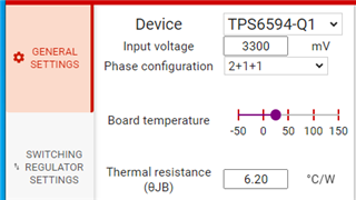
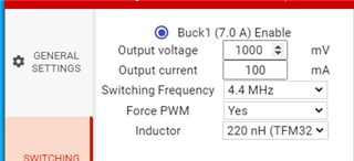
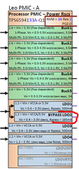
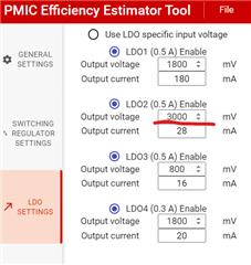
- TPS6594133A-Q1
best regards
cynthia