This thread has been locked.

If you have a related question, please click the "Ask a related question" button in the top right corner. The newly created question will be automatically linked to this question.

BQ24075: Default TMR Setting

Part Number: BQ24075

Hello,

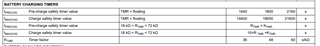
the datasheet of the BQ24075 states that if I leave the TMR Pin unconnected the timers will be set to the default values.

Can you please tell me what the default values are and is it save to connect a battery with any capacity to the BQ24075?

Best regards,

Stephan

  • I have connected a battery and now I'm seeing a strange behaviour that I wouldn't have expected before.

    SYSOFF is connected through a 100kOhm resistor to VBAT. When only the battery is connected the I can see that there is no voltage on the output of the BQ24075.

    But when I connect an USB Cable the charge LED is glowing and I can measure 5V on the output of the BQ24075, hence the battery is charging and the output MOSFET is conducting.

    My understanding is that the output MOSFET shouldn't conduct and the battery shouldn't charge when the SYSOFF Pin is high.

  • Hello Stephan,

    Thanks for reaching out on E2E. 

    When you plug in a USB cable then you should see a voltage on the output. Would it be possible to measure the current that is going to the battery? You can measure the voltage drop across a known resistance and use this to calculate the current, using a DMM in series to measure current is not recommended. 

    V/R

    Rafael Camarillo

  • Dear Rafael,

    I put a 100mOhm Resistor on the 5V Line of the USB cable and I measured a voltage drop of about 15mV across it.

    The battery I'm using is new and it seems to be charged in some way, it has a voltage of exactly 3,7V.

    Charge current is set to 500mA by the EN1 and EN2 pins.

    What I'm still confused about is that when SYSOFF is pulled high and I plug in the USB cable I can see the 5V on the output and the BQ24075 seems to be charging the battery, at least that's what the LED on the CHG pin seems to be indicating.

    The datasheet says: 'System Enable Input. Connect SYSOFF high to turn off the FET connecting the battery to the system
    output. When an adapter is connected, charging is also disabled.'

    I forgot: my dev board also has a 100mOhm Resistor between the BQ24075s BAT pin and the positive battery input. The voltage drop across it is 0mV with SYSOFF low or high. So the battery seems to be full.

    BTW, thanks for posting the table with the default timer values!

    Best regards,

    Stephan

  • Hey Stephan,

    If you look at the typical application circuit in the d/s, there are two FETs that are essentially used for the power path control. Lets call the one from VIN to OUT Q1 and the one from BAT to OUT Q2. When you power VIN, Q1 is on. So VOUT will be VO_REG. When the SYSOFF pin is pulled high then this disables the Q2 FET, this removes the BAT from OUT, and therefore charging is disabled. So whatever voltage that you have on VIN will still be on VOUT. With SYSOFF pulled high, would you be able to measure current to the battery? not the input current.

    Let me know if this makes sense.

    V/R

    Rafael Camarillo

  • Yes, I think I understood. But why is the CHG output low when SYSOFF is high?

    The datasheet says so too but why indicate charging when it actually isn't charging?

  • Hey Stephan,

    This is a good point and I agree its slightly misleading. If you look in the d/s section 9.3.5.5 Battery Disconnect, is states that the /CHRG output remains low when SYSOFF is high.

    BQ2407x Standalone 1-Cell 1.5-A Linear Battery Charger with PowerPath datasheet (Rev. N) (ti.com)

    V/R

    Rafael Camarillo

  • Can you confirm that the CHG output pin of the BQ24075 indicates charging while it actually is not charging?

  • Hey Stephan,

    Yes, I can confirm that the /CHRG pin pulls low, even when the SYSOFF is high. I do recommend that you double check that this is the case for your application. 

    V/R

    Rafael Camarillo