This thread has been locked.

If you have a related question, please click the "Ask a related question" button in the top right corner. The newly created question will be automatically linked to this question.

BQ25886: BQ25886 can not charge

Part Number: BQ25886

Hi 

I have a query need your help.

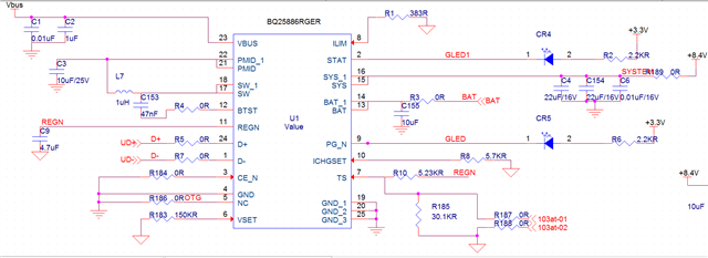
During the test, everything worked normally. When charging the battery, the STAT LED light started to blink.

The REGN voltage was 5.2V, the power supply voltage was 5V, the battery voltage (2 cells) was 7.4V, and the SYS voltage was 6.4 when the battery was disconnected. The circuit should be fine and it worked normally before.

Leave the CE pin floating, power on, then pull it low, and power on again. The circuit can charge normally, but after power off and power on again, it becomes unable to charge.

How to solve this issue.

Thanks

Star

  • Hi Star

    Can you send a schematic for review?

  • Hi Bill

    Thanks for your reply.

    The schematic as below.

    The reason has been found. The TS pin in the circuit is disconnected from the thermistor. After being connected, it can be charged normally.

    There is an anomaly. When the battery is disconnected during charging, normally the STAT LED should flash. Now after disconnecting the battery, the LED is always on.

    BAT is connected to a 10uF capacitor. When the battery is not connected, use an oscilloscope to measure its waveform, which is a high level of about 8.4V (zigzag P-P about 1.5V). There is no periodic discharge process.

    When measured the normal board, there is periodic charging and discharge process.

    Why the LED always on when the battery disconnect.

    Waiting for your reply.

    Thanks

    Star

  • Hi Star

    Thanks for the update on TS pin -- good news.

    Why the LED always on when the battery disconnect.

    Will check on this and update you.

  • Hi Bill 

    Any update?

    Thanks

    Star

  • Hi Star

    Why the LED always on when the battery disconnect.

    Have been looking at this in the lab and can duplicate it but have to add a system load.

    In your test is there a system load?

    When the battery is not connected, use an oscilloscope to measure its waveform, which is a high level of about 8.4V (zigzag P-P about 1.5V).

    Do you have a scope capture of the battery waveform?

    When measured the normal board, there is periodic charging and discharge process.

    Are these two customer boards that are behaving different?

  • Hi Bill

    Thanks for your reply.

    In your test is there a system load?

    Yes, there is a system load during test.

    This picture shows the waveform measured by BAT of the circuit connected to the load.

    This is the BAT waveform without load

    Please help check it.

    Thanks

    Star

  • Hi Star

    Thanks for scope capture.

    This looks like what I am seeing in the lab, will take a closer look and update you tomorrow.