This thread has been locked.

If you have a related question, please click the "Ask a related question" button in the top right corner. The newly created question will be automatically linked to this question.

TPS7A20: Please check my schematic on powering multiple ADS1256

Part Number: TPS7A20
Other Parts Discussed in Thread: ADS1256, REF6025

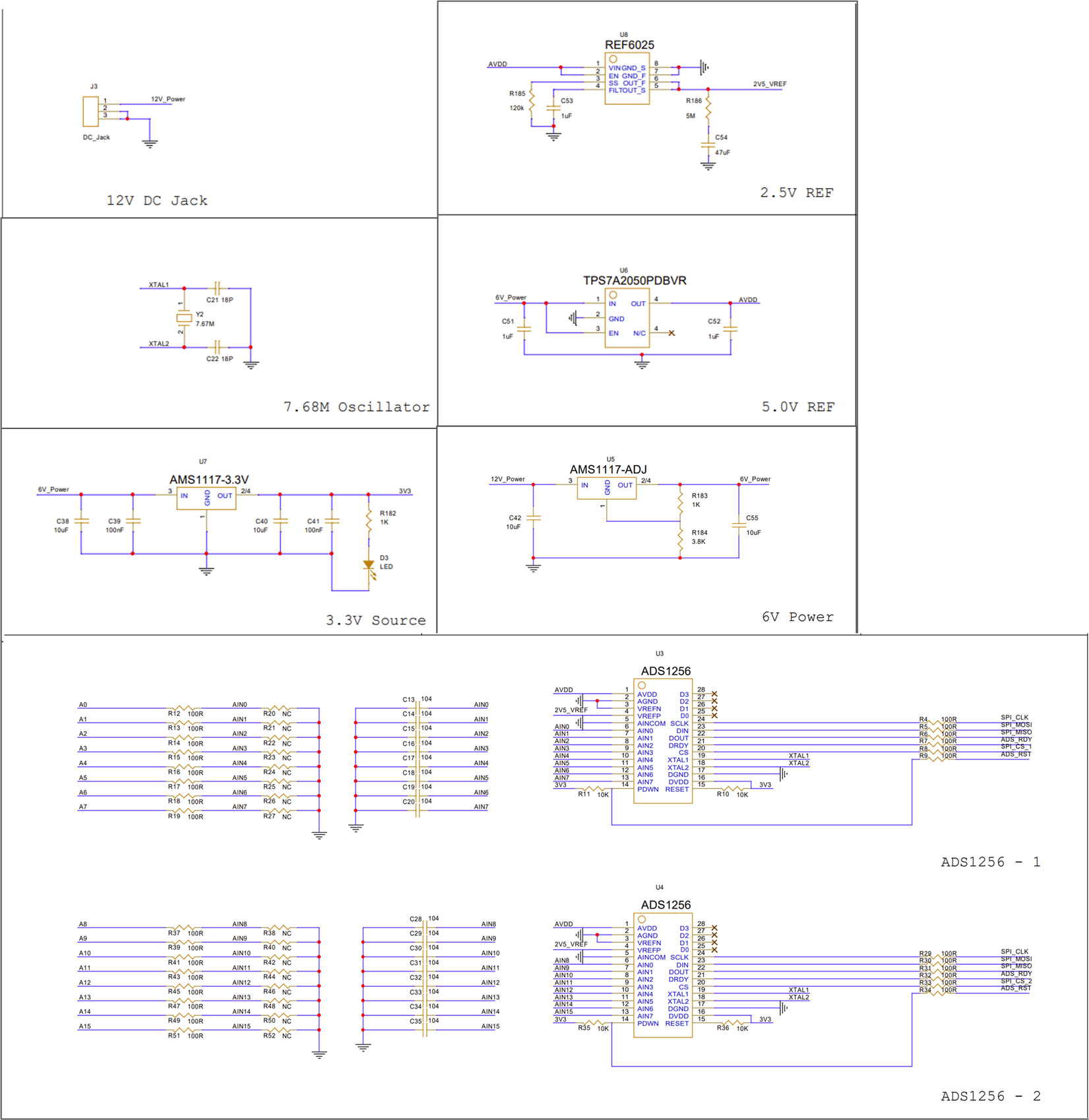
This is part of my schematic,

Based on ADS1256 datasheet, accurcy 5V AVDD and 2.5V VREF is essential.

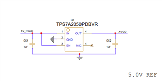
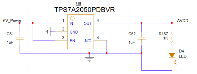
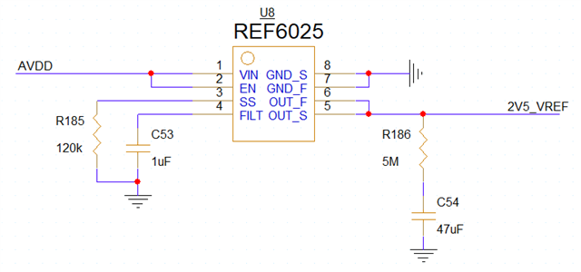
I try design a PCB that using REF6025 for VREF and TPS7A2050 for AVDD.

But I'm not sure whether these passive components can provide enough stability and accuracy on my board.

can anyone check the defination of those passive components for me?

  • Hey YC, 

    We typically recommend to ground NC pins for improved thermal performance. 

    Aside from that, as long as the 1uF COUT capacitor stays below the max spec for ESR, this application should be stable. 

    Please note that the EC table accuracy spec is characterized starting from 1mA - below that, the accuracy cannot be guaranteed as seen on the EC table. 

    You can add a light load to the output of the LDO, or I can loop in a marketing engineer to find a more appropriate LDO for your application. 

    Best,

    Juliette

  • Hi, Here's me modification,

    To avoid the current less than 1mA, I add a LED at output.

    (I'm not sure how much current do dual ADS1256 cost.)

    I want the AVDD to ADS1256 less loss as possible, Is this circuit enough to provide accuracy 5V?

    or, is there any better fixed output LDO?

    BTW, Does the REF6025 circuit need any modification?

  • Hi YC,

    Julie is out of the office today but she will respond to your latest question when she returns.

    Thanks,

    Stephen

  • Hey YC, 

    You will have to have the reference voltage team to check that schematic. I will reassign. 

    The LED output should be sufficient for the LDO accuracy. 

    Best,

    Juliette

  • Can I ask you about the appropriate accuracy of the capacitors and resistors in these two circuits?
    The current tentative decision is to use 5% 0805 resistors and 10% 0603 capacitors.

  • Hi YC,

    Here are my notes on your REF6025 portion of the schematic:

    1. You seem to have a 5 MOhm (mega-ohm) resistor in series with the output capacitor. This is too large. In the REF6025 datasheet there is a 5 mOhm (mili-ohm) resistor. This series resistor is used to keep REF6025 in stable operation. Sometimes a discrete resistor is required, sometimes not. I would suggest either using a small discrete resistor in the mOhm range, or following the suggestions in section 9.3.4 of the REF60xx datasheet to best fit your application.

    2. Please ensure a decoupling capacitor of at least 0.1 µF is placed from VIN to GND_F. More information can be found in section 11 of the REF60xx datasheet.

    3. Please see Section 12 of the REF60xx datasheet for layout guidelines.

    For REF6025, with correct application, 5% 0805 resistors and 10% 0603 capacitors should work fine.

    Thanks,

    Jackson