This thread has been locked.

If you have a related question, please click the "Ask a related question" button in the top right corner. The newly created question will be automatically linked to this question.

TPS25830A-Q1: Question about CC pin setting when using USB 2.0

Part Number: TPS25830A-Q1

Dear TI experts,

Last time I asked a review of the schematic using TPS25830A-Q1 ;

https://e2e.ti.com/support/power-management-group/power-management/f/power-management-forum/1292971/tps25830a-q1-please-review-the-schematic/4906065#4906065

Thanks to your review, initial test is done.

And I have another question from my customer.

They want to use data line with USB 2.0 (and CDP mode), not USB type C.

In this case what should my customer set CC1 and CC2? (pullup or pulldown, and the value of resistor) Could you guide about it?

Best regards,

Chase

  • Hi Chase,

    your customer just connect one of CC1/CC2 to GND by 5.1Kohm resistor.

  • Dear Alfie,

    THank you for your support.

    my customer did some tests with your guide.

    and here is one more question.

    - the connections is as below;

    [Desktop] <--USB A CABLE--> [TPS25830A] [MCU]

    1. connect desktop and TPS25830A-MCU side with USB A cable.

    2. After MCU is boot up (charger is CDP mode) then execute ADB server on TPS25830A-MCU side.

    3. on desktop side, execute "adb devices" command to check attached device.

    4. but right after boot up, desktop cannot detect nothing.

    5. And after disconnect USB cable and connect again, then desktop can detect device as below.

    Is there anything that I missed? I want to detect TPS25830A-MCU side on desktop even not reconnect cable.

    Please check this issue. Thanks.

    Best regards,

    Chase

  • Hi Chase 

    it's because Desktop output 5V Vbus, which make TPS25830A don't work. you can power on TPS25830A and then connect Desktop.

  • Dear Alife,

    Thank you for your support.

    You mean that I should first power on TPS25830A and then connect USB cable?

    And If I first connect USB cable and then power on TPS25830A will not work USB connection?

    Best regards,

    Chase

  • Hi Chase,

    yeah, if the voltage on Vbus is not 0V before TPS25830A power on, TPS25830A will not work. Desktop would output 5V voltage on Vbus if the Desktop is connected at first. recommend you to test the voltage on Vbus before TPS25830A power on when Desktop is connected.

  • Dear Alife,

    Thank you for your support.

    Here is one more question for my customer.

    End product would be Carplay module for Apple device. Would it be no problem for role change of carplay if we add 5.1K pulldown on CC1 or CC2 line?

    Best regards,

    Chase

  • Hi Chase,

    do you use type A or type C connector in your customer use case. if it's type A, the role of carplay is determined by DP,DM data communication. the pulled down resistor 5.1K will not have impact to the role.

  • Dear Alife,

    Thank you for your support.

    My customer still have a problem with testing Apple caplay. Could you check the questions below?

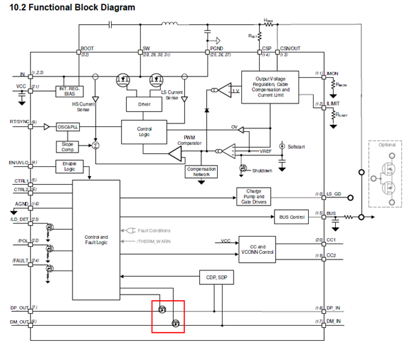
    1. in the function block diagram, DP and DM lines are controlled by 2 FETs (the red rectangle). These 2 FETs are controlled by "Control and Fault Logic". And "Control and Fault Logic" is controlled by CTRL1/CTRL2.

    Anyway what is the purpose of 2 FETs on DP and DM lines? colud it affect to Apple carplay role change?

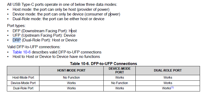
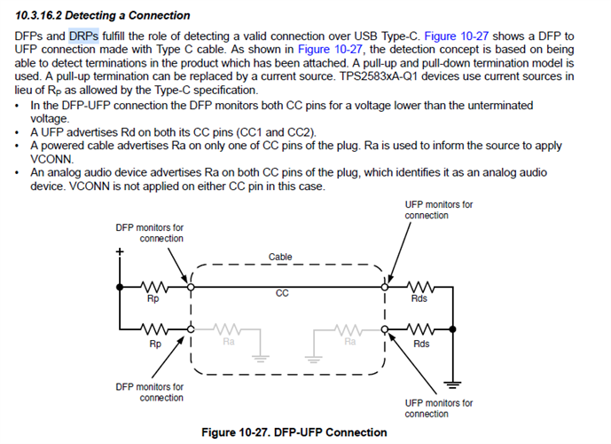
    2. In the datasheet, CC1/CC2 pins can detect the roles of TPS25830A-Q1. (DFP(host), UFP(device), DRP(host or device/dual role port))

    My customer did many SW test, but TPS25830A-Q1 always acts like host. So they doubt about CC pins setting.

    How about CC pins setting as DRP? Is it okay for USB2.0 communication and 5.0V voltage output?

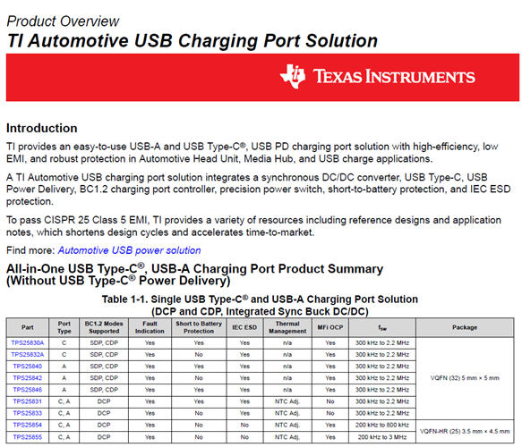
    3. Below image is the first page of SLVAF79-TI Automotive USB Charging Port Solution document.

    It says that TPS25830A supports type C usb ports.and other device can support both type A and type C.

    So my customer suspects that TPS25830A does not support type A USB communication. Could you explain it clearly?

    Please check this issue. Thanks.

    Best regards,

    Chase 

  • Hi  Chase,

    thank you reaching for us, please refer my input:

    1. there are the DP / DM switch in TPS25830A-Q1 for OVP protection, when the voltage on DP_IN and DM_IN exceed 3.9V, the switch will turn off to protect internal circuits. it have no impact to CarPlay.
    2. TPS25830A is not DRP device, it's DFP device. 

           3. TPS25830A usually use for type C application, but it also can be used for Type A port by connecting 5.1Kohm resistor on CC. we have had customer to use it for type A port.

    from where I am standing, the only thing TPS25830A need to do is to turn on the DP/DM switch during USB communication or carplay. is it OK for USB communication?

  • Dear Alife,

    Thank you for your support.

    2. TPS25830A is not DRP device, it's DFP device.

    -> I thought that if I use DRP device, then I can switch TPS25830A both host and device, so there would be a no problem with carplay role change.

    but as you said, DFP,UFP and DRP is only for the power concept, not USB communication.

    3. from where I am standing, the only thing TPS25830A need to do is to turn on the DP/DM switch during USB communication or carplay. is it OK for USB communication?

    -> I think it is okay, i will ask you more if I need.

  • Hi Chase,

    the conception of DRP,UFP,DFP is for power, and TPS25830A is a DFP device. yeah, please reach for us if you need~

  • Dear Alife,

    Thank you for your support, and hope you had a good weekend.

    This time they have a problem with USB HUB operation.

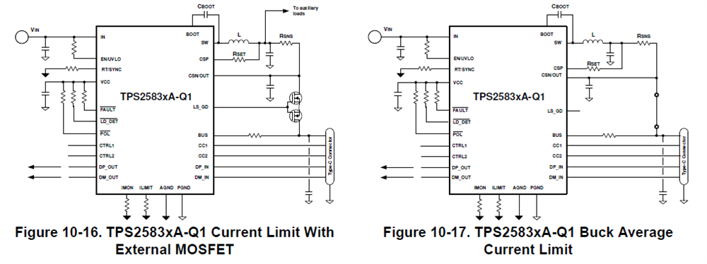
    1. What exactly do the MOSFETs in the figure 10-16?

    2. What do the TPS25830A in overcurrent situationin the fighre 10-17?

    3. Current my customer's schematic has no MOSFETs (like figure 10-16), and made cc pins connection as you suggested.

    Does it affect to USB HUB operation? (they see the message "USB Status timeout" and "Protocol Error".)

    Please check this issue. Thanks.

    Best regards,

    Chase

  • Hi Chase,

    In some applications, user would use CSN for a independent power source to auxiliary loads. in order to avoid BUS pin have impact to CSN, such as there are shorting to GND or shorting to Battery on BUS pin, we need add a back to back MOSFET between BUS and CSN pin. if you don't need CSN for a additional independent power source, the mosfet could be deleted.

    there are three current limit approach in TPS25820A, buck average current limit, cycle by cycle current limit and external mosfet current limit. for figure 10-17, there are no MOSFET between CSN and BUS. so there are only two current limit ways. the limit value of buck average current limit is determined by Rlimit resistor, the limit value of cycle by cycle current limit is 0.5*(ILS_LIMIT+IHS_LIMIT). figure 10-17 operating which current limit mode when overcurrent occur, it depend on which mode have more lower limit current value.

  • Dear Alife,

    Thank you for your support.

    1. You mean that If there are no auxiliary load, I don't need to add back to back MOSFET. -> Am I right?

    2. We can use 2 different ways to limiting current - 'buck average current limit' and 'cycle by cycle current limit'.

    Can I use 'cycle by cycle current limit' if I use a schematic just like figure 10-17? If so How can the IC recognize these 2 current limit methods?

    3. Do you think these current limit methods affect to USB HUB operation? (including CC pin configuration due to USB 2.0 communication)

    Best regards,

    Chase

  • Hi Chase,

    yes, I think you don't need back-to-back MOSFET in your customer applications.

    cycle by cycle current limit value is about 4.5A, if you set the buck average current limit is above 4.5A by Rlimit resistor, the device will come to cycle by cycle current limit way. if the buck average current limit is below 4.5A, the device will come to buck average current limit at first.

    from where I am standing, the current limit methods have no impact to USB Hub operation. from customer side, the device operate at current limit mode when the usb communication is abnormal?