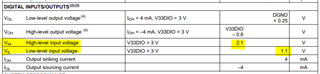
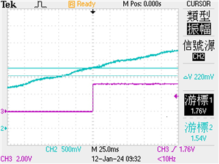
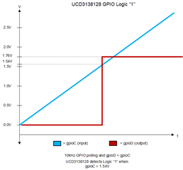
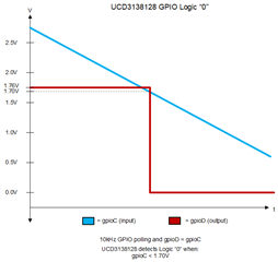
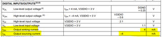
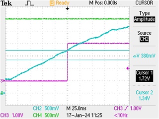
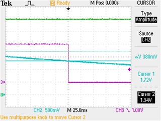
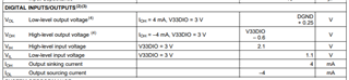
About SPEC VIH > 2.1V is High-level and VIL < 1.1V is Low-level , Why test result : VIH > 1.6V is High-level and VIL < 1.6V is Low-level,no voltage window?

-
Ask a related question
What is a related question?A related question is a question created from another question. When the related question is created, it will be automatically linked to the original question.