I have a design based on the LM3444 (using the typical application circuit) that is not behaving as specified in the datasheet.
On initial turn on current ramps up in the inductor and overshoots the setpoint applied at the FILTER pin. This can be seen in the below scope trace:
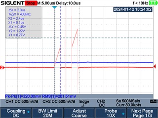 |
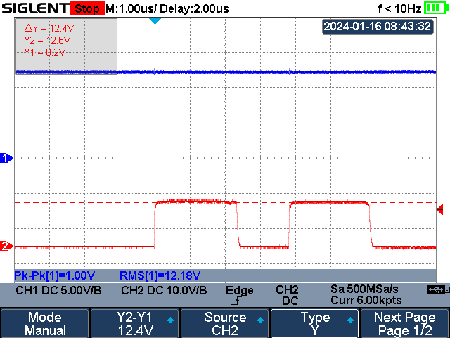
In the this image the blue trace is the voltage applied to the FILTER pin and red is the voltage at the ISNS pin (across the sense resistor) |
As can be seen the ISNS voltage overshoots the FILTER voltage and continues to ramp up to 770mV before switching off.
I have purchased a reference implementation (LM3444-EDSNEV/NOPB) and performed the same measurements. A scope trace of this can be seen below:
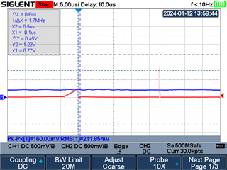 |
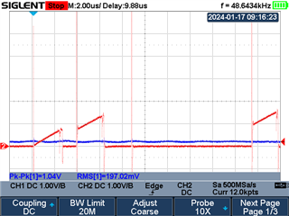
In the this image the blue trace is the voltage applied to the FILTER pin and red is the voltage at the ISNS pin (across the sense resistor) |
As can be seen this circuit behaves as expected; the ISNS voltage climbs until the setpoint is reached and the MOSFET switches off halting current.
Attached is a copy of my schematic, what could be causing the LED Driver to not be switching off at the setpoint?