This thread has been locked.

If you have a related question, please click the "Ask a related question" button in the top right corner. The newly created question will be automatically linked to this question.

LP2998-Q1: Can VDDQ be connected to PWM to dynamically adjust the output of VTT?

Part Number: LP2998-Q1
Other Parts Discussed in Thread: LP2998EVAL,

Hi team,

Hope you‘re doing well!

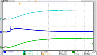
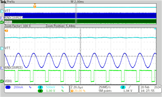
1、What is the delay/calculation between VTT and VDDQ?

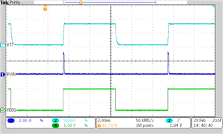
2、Can VDDQ be connected to PWM to dynamically adjust the output of VTT?

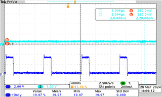
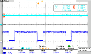
3、How will VTT output if VDDQ inputs a 3.3V PWM?

4、If it can be realized, is there any relevant schematic diagram or simulation that can be provided?

5、Neither Ti.com nor Tisample has LP2998EVAL. Is there any other ways which I can apply to obtain LP2998EVAL?

Thanks!

  • Hi Guohai,

    1. I don't see a standardized delay spec for VDDQ to VTT. PVIN, AVIN, and VDDQ are all needed for VTT output so the delay will depend on which signal ramps up last. I would use an EVAL board to get a complete measurement. We don't have easy access to sample boards for this part since it's a legacy device so for the quickest result I would order one from TI.com or contact the marketing team for other options.
       
    2. VTT can be dynamically adjusted by changing the VDDQ input but you will need to make sure that any changes in VTT don't negatively affect the DDR system downstream. I'm not sure how you would use a PWM for this rather than just adjusting a static DC input.

    3. With VDDQ at 3.3V I would expect VTT = VDDQ / 2 = 1.65V. Keep in mind that VDDQ voltage must be less than 2 x (AVIN - 1) or 6V, whichever is smaller.

    4. There are schematic example shown in Section 9.2 of the datasheet and also in the following EVM User's Guide: AN-1813 LP2998 Evaluation Board (Rev. A)
       
    5. I'm seeing an EVAL board available on TI.com: https://www.ti.com/tool/LP2998EVAL

      On my end it says the boards are in stock.

    Regards,

    James

  • Hi James,

    The customer said that he saw a product on the market that uses LP2998-Q1 like this:


    VDDQ inputs a 3.3V PWM, and adjusts the duty cycle of this PWM to achieve VTT adjustment between 0-1.65V. This is not applied to DDR, but is used to dynamically adjust the brightness of the monitor.


    1. Is this application feasible? Could please you confirm it for me? 

    2.I logged into Ti.com again and the inventory did appear. Are there free EVM that can be given to customers?

    Thanks!

  • Hello Lin

    The device expert is out of office due to public holiday in US. Please expect delay in response by tomorrow. 

    Best regards,

    Ishtiaque Panhwar

  • Hi Guohai,

    1. I don't think VTT has any sort of undervoltage check so whatever you feed from VDDQ should be divided down to VTT (VTT = VDDQ / 2). Most of the specs are for specific DDRx target voltages but the VTT output is only based on the VDDQ input. This is something the customer would need to test themselves as I don't have access to any board samples but you should be able to control VTT to a wide degree if you have a dynamic VDDQ.

    2. Reach out to the marketing team to see if a ZST order can be set up in this case. Otherwise you will need to purchase boards directly.

    Regards,

    James

  • Hi James,

    Could you help test the output voltage of VTT when the VDDQ input is a PWM ?. The EVM I applied for has not been shipped yet. Thanks!

  • Hi Guohai,

    Since this is an older part, we don't have access to immediate samples of this EVAL board so I would be subject to the same shipping times from the product distribution center unfortunately.

    Regards,

    James

  • Hi James,

    I used the EVM to do test and found that PVIN will generate an Inrush current when VDDQ  power on. As the VDDQ frequency increases, the current will surge.

    This is how I connect:

    This is the waveform at startup using a linear power supply to power VDDQ (channel 1 blue is the Pvin current):

    This is PWM when VDDQ is 1.5V (100Hz):

    This is PWM when VDDQ is 1.5V (50KHz):

    I set a 200mA limit on the input current of Pvin. If the limit is relaxed, the Pvin current will be as high as several amps.

    I want to know, why does it draw such a large current when there is no load on the VTT? What are these currents used for?

    Thanks!

  • Hi Guohai,

    This kind of dynamic input application is not something we test for. Usually the input is stable during operation.

    Also, you are changing the voltage on 3 input pins at once (VDDQ, PVIN and AVIN). From our earlier discussion, I assumed that only VDDQ would be changing and the other inputs would be held steady. I don't know if only changing VDDQ would affect the inrush profile but changing all three inputs could have unexpected behaviors.

    The block diagram below shows the device internals. The current you are seeing could be going to GND somehow through a low internal impedance. If you have all the output pins floating unloaded, there's no where else for the current to go.

    As I mentioned before, this is an untested use case so I don't have much input to share on the behavior. The switching frequency also seems high. Adjusting the VTT output multiple times a second seems excessive. Usually the DDR has a static source operation point.

    Regards,

    James

  • Hi James,

    I tried again and raised the PWM frequency connected to VDDQ to 1MHz, which enabled this function. There was no abnormality in the current.

    By adjusting the frequency, we found that the current of PVIN & AVIN is very large when it is below 200KHz, but after it exceeds 300KHz, the phenomenon of large current no longer occurs.

  • Hi Guohai,

    James is going to be out of office until Tuesday, so please expect a delay in his response.

    Best regards,

    Matt

  • Hi Guohai,

    As I mentioned above, this type of input scheme hasn't been tested for this device so the limits of this application are unknown. If you are able to achieve your desired behavior on VTT, then that's fine but I don't have any further comments on the specific frequency limits of this input type.

    Regards,

    James