This thread has been locked.

If you have a related question, please click the "Ask a related question" button in the top right corner. The newly created question will be automatically linked to this question.

BQ79600-Q1: SPI_RDY not going high after Read Command Frame

Part Number: BQ79600-Q1
Other Parts Discussed in Thread: BQ79616, USB2ANY

Hello,

We are using a BQ79600 as a bridge device betweeen our MCU and multiple BQ79616 devices in a stack to read out cell voltages and temperatures. We use a STM32G431C8T6 as our MCU.

We have followed the datasheet of the BQ79600 for the wake-up, shutdown and auto-adressing sequences. We were succesfull in turning on the BQ79600 with a wake-up ping and turning on the BQ79616 by setting the CONTROL1 register. We were also able to shut down the BQ79616 by setting the CONTROL1 register.

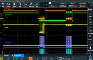
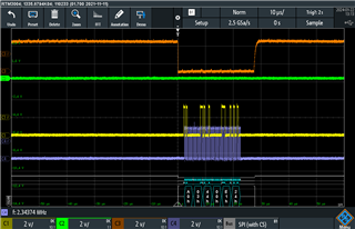
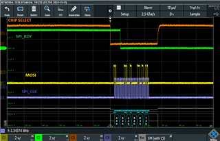
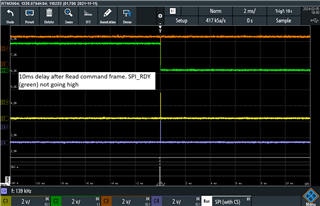
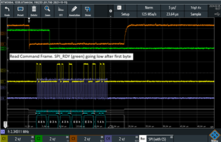
The problems start with the auto-adressing sequence. All stack and individual (dummy) writes seem to be working. The (dummy) reads however do not work. I have included a picture (Read command frame) showing our wave forms when sending the read command frame. This waveform is the result of following function: SpiReadReg(0, OTP_ECC_DATAIN1, response_frame2, 1, STACK_READ);

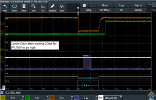
Within the SpiReadReg function a read command frame write is performed. As seen in the wavefrom the SPI_RDY line goes low 5µs after the first byte (0xA0 = Stack Read) as expected. After this we wait for SPI_RDY to go high with a timeout. SPI_RDY however never goes high and we are forced to perform a COMM_CLEAR which resets the SPI_RDY line correctly.

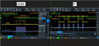
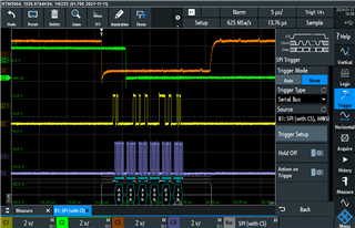
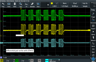
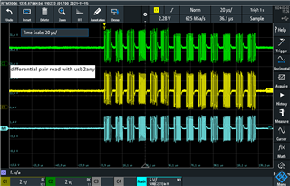
We have used the TI USB2ANY device to send commands via the BQAutoEval software in which we mirror every spi message send from code. When using the USB2ANY connection we are able to successfully send a read command frame and receive data. In the attached image (TI Eval Board SPI_RDY going High) we see the SPI_RDY line go high after a while. In the attached image (Difference IN Read Command Message) the wavefroms created by our STM32 when performing the read command frame and the waveforms created by the USB2ANY device are shown side by side.
The only difference is that with the USB2ANY the SPI_RDY line eventually goes high while with the STM32 it stays low indefinetly. All previous SPI commands are the same and this is the first read performed.

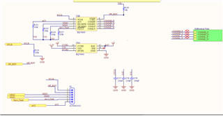
We are using the motorola SPI mode within the STM32 and are not using NSS but rather setting and resetting the chip select manually in the code. We are using a bit rate of 4.6Mbit/s which is in the 2-6Mbit/s range required by the BQ79600. We are using a custom PCB, we are sure that the BQ79600 turns on by measuring 1.8V on the DVDD pin once the wake-up ping is send. Attached there is a screenshot of our pcb schematic, note that the resistors connecting SIMO,MISO,nCS and SCLK were all changed to 10K in accoradance with the datasheet.

Do you have any idea how to tackle this problem?

We look forward to you answer.

  • I forgot to attach our read command frame image in the initial post.

  • Hi,

    Thanks for including all of this information. This can be caused by a number of things including an incomplete frame, a comm clear being sent by a device in the stack, or something else. To start debugging, can you check a few things?

    1. The GUI sends out commands very slowly. What is your SPI frequency when using the MCU? Do you see an issue when you decrease the rate at which you send commands?

    2. Does the 600 device have any communication faults or any faults at all when this happens? I'd be especially interested in COMM_CLEAR_DET

    Let me know what you find. 

    Best,

    Nancy

  • Hello,

    Thanks for the fast reply.

    We use a prescaler on the CLK to set our SPI frequency. The only prescaler values that are within the required 2-6Mhz range are 4.68Mbit/s and 2.34Mbit/s. Both of these options have no influence on the problem and seem to work exactly the same.

    We tried reading the fault by generating it with the MCU and reading it out via the GUI but this did not seem to work. As the fault only occurs when sending SPI messages via the MCU and we are unable to read any registers due to the initial problem of SPI_RDY not going high we can't read the fault registers when the fault occurs. Any suggestions on how we could read out this register?

  • Hi,

    Right, that makes sense that you cannot read the faults. Is there a way you can probe the NFAULT pin on the device(s)? This is an active low pin, so if there is a fault it will pull this voltage low. This won't tell us what type of fault is there; we may have to find a workaround for that. 

    Best,

    Nancy

  • Hello,

    In the following images we have generated the same situation where SPI_RDY does not go high. In the other image the green line shows the fault pin from the BQ79600. As you can see this line is not high before the spi_rdy pin goes low and does not go low. Does this indicate that there are no faults?

    The fault line goes high initially on start-up after which it goes low again. After this it never goes high again. The fault pin is correctly pulled up by a 100k resistor.

  • Hi,

    The NFAULT pin will pull low when there is a fault. This could be caused by the digital reset that happens when the device wakes up, in addition to a cause for this issue. Unfortunately, we cannot clear the faults after the wake ping to see if something with the dummy writes is definitively causing a fault. There are two more things we can try:

    1. What is the delay between commands for the dummy writes? The GUI has delays >5uS which may be helpful. 

    2. Is it possible to probe the COMH/COML pins of the base device? I wonder if we can see a problem with the stack VIF communication. 

    Best,

    Nancy

  • Hello,

    Sorry for the late answer. We already had a substantial delay between the read request frames from the dummy writes. I changed it to wait 15µs before performing the read command frame but the problem persisted. This delay is between each message not between each byte. As we are using a library which performs the low level spi for us we can't control the delay between each byte being send. Could it be that this is the cause?


    I have attached the wavefroms of COMH and COML read out when sending a write command with the USB2ANY device and with our STM32. To us these signals look identical. The blue wave is C1-C2 and is the differential signal.


  • Hi, 

    The delay should be the delay between commands, as you implemented it. 15uS should generally be enough but just to check, can you try with a delay of 1-10ms?

    Best,

    Nancy

  • Hello,

    I have implemented a 10ms delay after the read command frame. Attached a close up of the frame where spi_rdy goes low can be seen. Also attached is a zoomed out image of spi_rdy staying low for the full 10ms. After this a COMM CLEAR happens which can be seen in the final image, this resets the spi_rdy.

  • Hi,

    Thank you for trying this. I think this may need additional debugging via email. I will friend you on E2E then we can exchange email addresses via private message. 

    Best,

    Nancy