This thread has been locked.

If you have a related question, please click the "Ask a related question" button in the top right corner. The newly created question will be automatically linked to this question.

TLV717P: 12V 150-mA, Low-Dropout Fold-back Current Limiting IC

Part Number: TLV717P
Other Parts Discussed in Thread: TPS1H000-Q1, TPS7B7701-Q1

I'm looking for a 12V 150mA fold-back current limiting IC with low-dropout (12V input and 12V output) for a high reliability and high efficient power supply project.

I tried some Single-Channel Smart High-Side Switches, but they didn't meet my needs because they only offer constant current or hic up limiting modes with an ON time longer than 1msec. I'm looking for a Fold-back IC or smart switch that can limit the current to 150mA in a fold-back manner or a hic up Smart Switch that has an ON time shorter than 1msec.

Do you have any suggestions or recommendations for such a device?

Kind regards

  • Hi Souheil,

    To make sure I'm understanding your use case correctly, which of these situations most accurately reflects what you're looking for?

    (1) Nominal current is 150mA, with a desired foldback current limit to a lower current (ex. 70mA)

    (2) Nominal current is higher (ex. 1A), with a desired foldback current limit to 150mA

    (3) Nominal current is 150mA maximum, and 150mA or lower output current during a current-limit event is OK

    If it's none of these, feel free to explain further or add nuance as needed.

    Can you please also help clarify if by "ON time shorter than 1msec" you are referring to the time between (a) the LDO being enabled, to (b) output voltage fully ramped at 12V? 

    Based on your responses, I can give the best recommendation.

    Regards,

    Kelsey

  • Firstly, the situation number 3 is close to what I'm looking for, with these additional details:

    The Current Limiting IC shall handle short-term over-current transients of up to 150mA for a maximum of 1ms without triggering the over-current protection and without experiencing any damage. If the current exceeds 150mA for 1ms, the voltage will be lowered to keep the current lower than the 150mA limit.  The IC will stay in this 'fold-back' mode until the over-current condition is cleared.

    Secondly, to avoid any confusion about the ON time, I am referring to the hiccup ON time. You can find more details in the document TPS1H000-Q1, under "Figure 19. Auto-Retry-Mode Example". This figure illustrates the hiccup ON time and OFF time during the Auto Retry Mode.

    Kind regards

    Slim

  • Hi Slim,

    Thanks for the clarification! I think the best option we have would be TPS7B7701-Q1, which has an adjustable current limit that you can set with a resistor on the LIM pin. This device doesn't have foldback current limit, but based on the use case you're describing, I think it may still be OK.

    If the current limit is set to 150mA, this device will enter current limit at 150mA, maintain 150mA, and the output voltage will be lowered to 1.233V (typical). This behavior is maintained until one of three things happens:

    (1) The current limit event is over. In this case, the LDO will begin to regulate at nominal expected values again.

    (2) The device is disabled from an external source (ex. an MCU monitoring the LDO takes action to disable the LDO).

    (3) The device overheats and goes into thermal shutdown, at which point the LDO output turns itself off until the hysteresis temperature is reached (i.e. until it cools off enough to regulate again).

    Current limit accuracy is 8% maximum across all conditions.

    I looked at the datasheet for TPS1H000-Q1, and if I'm understanding the hiccup timing requirement, your need is for IOUT to toggle high for <1ms. TPS7B7701-Q1 doesn't have an auto-retry mode with hiccuping, so IOUT will not exhibit any toggling/pulsing behavior, it will instead behave similarly to the waveform in Figure 15 of TPS1H000-Q1's datasheet, where the maximum IOUT will be 150mA (or whatever IOUT is set as the current limit by the external resistor on the LIM pin). The difference with TPS7B7701-Q1 is that it will internally monitor the current, and if the current goes below the current limit threshold, it will begin to regulate normally again.

    Let me know if I'm understanding this correctly; I think TPS7B7701-Q1 should work here.

    Are you able to share what the end equipment is and what the LDO will be powering?

    Regards,

    Kelsey

  • Hi Kelsey,

    You stated that if the current limit is set to 150mA, this device will enter current limit at 150mA, maintain 150mA, and the output voltage will be lowered to 1.233V (typical). I would like to know where you got this information from I can't find in the datasheet. Also, when the 150mA limit is detected, is it possible that the Iout decrease below 150mA to 100mA or 40mA until the short circuit is cleared.

    Additionally, I would appreciate your help in finding a chart that shows how the output voltage of the TPS7B7701-Q1 varies with the output current . I am interested in seeing how the output voltage drops when the current limit is reached. This would help me explain the foldback behaviour of this device.

    Finally, what is the time base in Fig 13 to Fig 17.

    This LDO will be powering a portable devices.

    Kind regards.

    Slim

  • Hi Slim,

    You stated that if the current limit is set to 150mA, this device will enter current limit at 150mA, maintain 150mA, and the output voltage will be lowered to 1.233V (typical). I would like to know where you got this information from I can't find in the datasheet.

    Thanks for following up on this - I realized this is actually incorrect. The output voltage will not be lowered to 1.233V; VOUT will be reduced to some intermediate value between the nominal VOUT and 0V. My mistake before was conflating VOUT voltage with the voltage on the LIM pin when output current is limited, which is spec'd at 1.233V in the EC table of the datasheet.

    Also, when the 150mA limit is detected, is it possible that the Iout decrease below 150mA to 100mA or 40mA until the short circuit is cleared.

    No, IOUT will be maintained at the set current limit (in this case 150mA) and not be reduced. Instead, VOUT will be reduced, and if the power dissipation across the LDO during the current limit condition is high enough, the LDO will go into thermal shutdown and disable itself. Based on your operating conditions, though, I wouldn't expect the LDO to go into thermal shutdown. Assuming a very small input to output voltage differential (ex. 1V or less) and max  IOUT of 150mA,  that would be 0.15W dissipated across the LDO, which corresponds to only a ~7°C LDO temperature rise on top of ambient temperature. In current limit, VOUT can be reduced to an even lower value without a concern of thermal shutdown (as long as the ambient temperature isn't expected to be high). Relevant equations here are:

    Power dissipation = (VIN - VOUT)*(IOUT)

    LDO temperature rise = (Power dissipation)*(thermal resistance, RθJA)

    LDO temperature = (LDO temperature rise) + (ambient temperature)

    RθJA is unique to each LDO and can be found in the datasheet for each respective device.

    For your questions about VOUT varying with output current during current limit and the time base on Figures 13-17, I will check with our applications team. If the graph of VOUT doesn't exist, I can try to locate a similar graph from a different device that has the same current limit behavior. I was just looking at one the other day but can't seem to locate it right now. I think this will help also clarify my response to the first question re: VOUT at "some intermediate value."

    Regards,

    Kelsey

  • Hi again,

    I got feedback that the timescale for Figure 13-15 is 100μs/division, and the timescale for Figures 16 and 17 is 200μs/division.

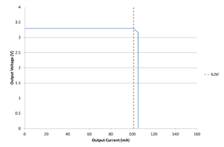
    Also, we don't have a specific graph for TPS7B7701-Q1's output voltage behavior in current limit, but it can be generalized to brick wall current limit behavior of LDOs in general.

    Below is an image from our LDO Basics guide that showcases the VOUT and IOUT brick wall current limit behavior. As you can see, once the current limit is hit, IOUT is maintained, while the output voltage falls somewhere between nominal VOUT and 0V (i.e. the vertical blue line). It's unknown exactly what voltage the LDO output will be at when its operating in current limit.

    Regards,

    Kelsey

  • For the Single-Channel TPS7B7701-Q1, the current limit is programmed by selecting the external resistor between the LIM pin and return GND. The datasheet states that this pin does not require an external capacitor.

     Question:

    I want to set the current limit to 150mA, which can be achieved by choosing the appropriate resistor at the LIM pin. However, I also want to enable the IC to tolerate a short burst of 150mA for up to 1ms. Is there a way to delay the current limiting foldback by adding a suitable delay capacitor across the external current limiting resistor at the LIM pin?

    Could you please consult the expert of the TPS7B7701-Q1 and find out what value of delay capacitor is needed to obtain 1ms delay.

    Here is the exact requirement:

    -Over-current protection shall withstand short-term over-current transients of up to 150mA maximum for a maximum of 1ms without activating the over-current protection and without damaging the IC.

    - Once activated, the IC 'fold-back' mode of over-current protection shall be persistent i.e. stay in ‘fold-back’ mode until the overload is removed.

  • Hi Slim,

    Let me check on this for you and get back with an answer in 1-2 business days.

    To be clear, though, the behavior of TPS7B7701-Q1 is brick-wall current limit. The IC does not reduce the output current while in current limit. Typically the "foldback" of foldback current limit in relation to LDOs refers to the reduction of output current while in current limit, and that is not the case here. I just want to make sure we're aligned on the behavior that can be expected.

    Also, there is a tolerance associated with the adjustable current limit of TPS7B7701-Q1, which is 8% maximum across all conditions. Please consider this when designing, because if 150mA is the absolute maximum output current the output rail of the LDO should allow, there should be a bit of a buffer designed in for the tolerance of the current limit. Setting current limit at 150mA, for example, could result in current limit triggering at maximum 162mA.

    I'll get back to you soon with an update.

    Regards,

    Kelsey

  • Hi Slim,

    What are the minimum and maximum values of current limit you'd like to design for? This will help us figure out if a capacitor is needed and what size.

    If you set up your current limit so that the minimum value where it triggers is 150mA, then a cap on the LIM pin is not necessary. On the other hand, if you want your current limit to trigger with a maximum value of 150mA, then we can try to figure out how much capacitance we would need to slow the voltage rise at the LIM node.

    Regards,

    Kelsey

  • The current limit should be set in the range of 130mA to 140mA. . However, the IC shall withtansd short-term over-current transient of 150mA for a maximum of 1msec.

  • Hi Slim,

    I've talked this over with a couple team members, and we believe a capacitance can be chosen based on t=4RC, with the cap in parallel with the resistor on the LIM pin.

    The first step is to choose a resistor value for RLIM, which can be calculated via instructions found in datasheet section 8.2.2.4: Current-Limit Resistor Selection. I calculated using maximum output current of 150mA, and the resistance I got was 1.758kΩ, so the typical resistor value that would be best would be 1.78kΩ. Sizing this up slightly compared to the calculated value is a conservative estimate, as higher RLIM results in a lower current limit.

    So the capacitance needed to achieve a 1ms delay would be 0.14μF, based on 1ms=4*(1.78kΩ)*C.

    This is a typical capacitance value to achieve 1ms delay, and actual delay time will depend on what the load current draw is during the short circuit condition. If the current draw is 500mA, for example, there will be less of a delay than if the current draw is just 151mA. In both cases, current limit will be triggered, but the higher load current will drive a faster response (=less of a delay). What is the current draw condition for which you're expecting 150mA to be exceeded? If it's a larger current draw, it might be best to size up the cap a small amount.

    Regards,

    Kelsey