This thread has been locked.

If you have a related question, please click the "Ask a related question" button in the top right corner. The newly created question will be automatically linked to this question.

LMR33630-Q1: LMR33630AQRNXRQ1: 3.3V-out tolerance range

Part Number: LMR33630-Q1

Hi Sir,

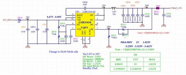
We knew the electrical characteristics of the datasheet that provided typical values at TJ = 25°C, my customer is asking for how to calculate the 3.3V-out tolerance range at TJ = -40C ~ +85C.
If the LMR33630AQRNXRQ1 is working at TJ = +85C, is the Vfb value different from TJ at +25C?
Except Rfbt, Rfbb, and Vfb, are there any parameters that need to be considered? (Rfbt and Rfbb both are used 1% tolerance)
Or is there any document or calculation formula that can share with them?
  • Hello

    I think it is best to use the tolerance values in the data sheet for Vfb; +/- 1.5%.  Even though they apply to -40C to 125C; they will

    give you some margin at 85C.  Then you can apply your tolerance for your Rfbb and Rfbt.  Note that at light loads the output voltage

    will go up.  This is shown in the data sheet regulation graphs.  At no load, there will be about a +1% increase in the output voltage.

    Thanks

  • Hi Sir,

    Calculated the output voltage tolerance range, just needs to consider Rfbt, Rfbb, and Vfb for Equation 3? Does it not need to consider other parameters (ex: inductor, output cap, or others)? is it right?

    The output current drops to how much current value and the system will change mode from PWM to PFM?

  • Hello

    It is a good approximation to consider just the Vfb and the resistor tolerance.

    The exact load current when the device switches from PFM to PWM will depend on the input voltage,

    output voltage, switching frequency and inductor value.  

    Please see the curves in the data sheet for examples of how the frequency changes with load.

    Thanks