This thread has been locked.

If you have a related question, please click the "Ask a related question" button in the top right corner. The newly created question will be automatically linked to this question.

UCC256404: Won't start up - keeps cycling

Part Number: UCC256404
Other Parts Discussed in Thread: UCC28064,

Hi, I have a dual UCC28064 PFC stage creating 400Vdc at 1.1kW.  I have a few issues with that, but subject of another thread.

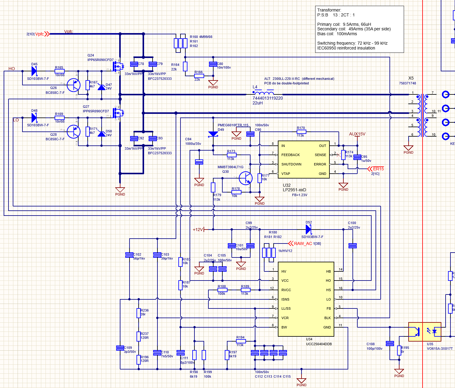
This stage feeds into a UCC256404 LLC stage, intented to switch to 30V DC at 1.1kW.

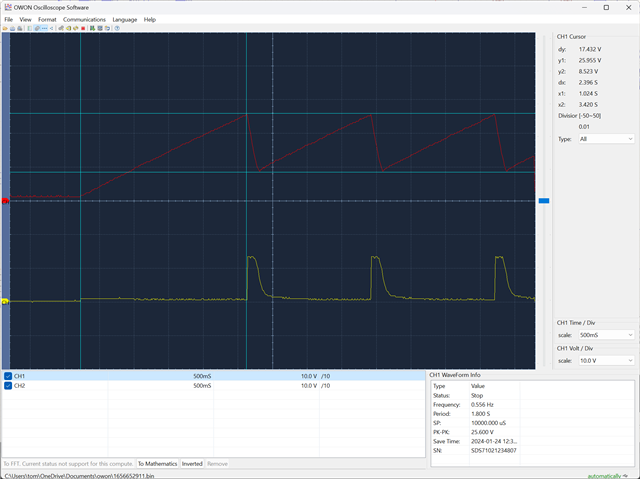
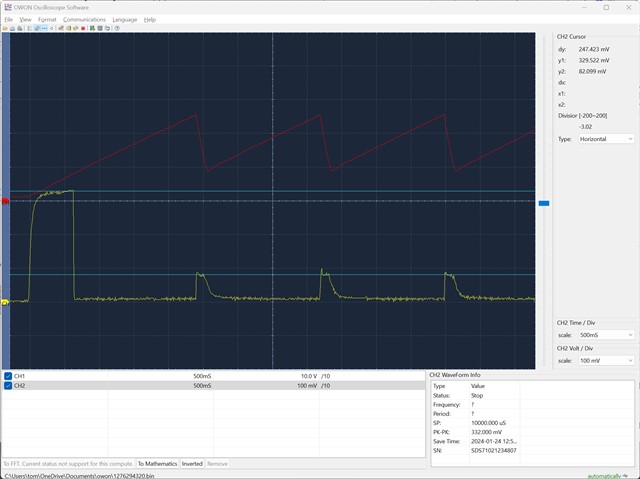
The problem I've got at the moment is that is isn't even powering up.  I seem to try, and I get the AUX15V for 1/2 second before it cuts out and 2-3 seconds later it tries again.  My circuit is based on the reference design, so are them some ideas what I should be looking at to get it up and running?

  • Hello,

    I am reviewing your inquiry and will get back to you shortly.

    Regards,

  • Hello,

    If the design is cycle VCC more than likely it is a fault.   It most likely will be over current or over voltage.

    You should be able to determine which fault it is by studying VCC, BW, ISNS, SS with an oscilloscope.

    Once you have determined what fault is shutting the design down then we can make suggestions on helping you trouble shoot and fix the design.

    The following link will bring you to an excel design tool that you can use to check your design as well.

    https://www.ti.com/tool/download/SLUC675

    Regards,

  • Hello Mike - thank you for taking the time to help me out here.  I have tried powering with an external VCC and it is still cycling around 1s and I see no activity on the HO or LO lines.  My voltage at BLK was 1.1V, but as an experiment, I adjusted to 1.8V and that made no difference.

    I read somewhere on here about grounding BW to eliminate some element of the logic and take it out of the equation - is that worth doing to see if it helps?  I'm dubious because I'm seeing no voltage on BW anyway.

    I see VCC ramping up to 26V, at which point RVCC switches on (this turns on the PFC) but then very quickly it all shuts down and it cycles again...

    Throughout this there is no activity on LO, and I also see nothing on BW or ISNS.

    This is what I see on LL/SS...

    So, it looks to me like it's getting through the first couple of stages of boot-up, but I would then expect to see LO start to switch, in order to charge the high-side gate voltage, but something is stopping it.   Any ideas, or is there something else I can probe to help diagnose?

    Regards, Tom

  • Hello,

    Your design looks like it is cycling VCC which will happen during fault.   I think CH1 is VCC and I am not sure what CH2 is.  In the future could you label and tell be what your scope plot channels are; as well as, test conditions?

    Your VCC capacitor is 1000 uF.  VCC during startup goes from 0 to roughly 27 V than cycles between roughly 27 V and 9.5V  During the VCC capacitor discharges the ICC current based on C*dv/dt is 92 mA.

    This would indicate that there is some loading in your design.

    When your ICC current (ICCrun) when driving FETs is 2.7 mA maximum.  Your design shows that there is 92 mA of ICC current based on VCC discharge.  Are you sure the design is not switching?

    Can you double check the design to make sure it is not switching?  Could you probe VCC, LO, SS and BW all at the same time and have them all on the same plot.  You can start by triggering on LO to make sure the design is not switching.  I believe you will find that it might be switching.

    Regards,

  • The 92mA on VCC makes some sense - this is roughly the draw I see on the bench supply when running the PFC from an external supply.

    Apologies for not labelling my plots - the first one was VCC (red) and RVCC (yellow).  So shows that once JFET has finished, it is switching on the regulator  but is immediately discharging as it is powering the PFC.  This concept is as per the reference design, and I assume if it were switching correctly, is fine.

    The second plot (duplicated for some reason) is VCC (red) and LL/SS (yellow).  I'm not sure what this is showing us, but it seems to be doing something so thought might be helpful

    I'll try to knock up plots with more traces, but I have a technical barrier in only having a 2-trace scope, so I'll be gluing some traces together.

  • I've rerun the tests, attempting to trigger on LO - but there is just no activity on that pin - it stays at 0V throughout.  Likewise BW stays at 0V - but that is not surprising given LO doesn't do anything.

    BLK is at 1.2v when the PFC is off and jumps to 1.8V when the PFC is running.

    I've also re-run the tests with the PFC running from a bench supply.  I don't see the power cycling issue - VCC remains at 15V, RVCC remains at 13V, BLK remains at 1.8V.  SS/LL jumps slightly from about 60 to 100mV on a 1 second cycle.  No activity at all on LO or HO.

  • Hello,

    I am reviewing your inquiry and will get back to you shortly.

    Regards,

  • Hello,

    I am starting to thing there might be something wrong feedback wise.  If the output voltage is not up and you have VCC the design should be switching.

    If possible can you use a DC supply to supply the LLC and disable the PFC part of the circuit?  This will let us focus on the LLC.  You can diode or in a bias supply to VCC to ensure it has voltage make sure to bring it above UVLO.

    I would start by looking at the FB pin to check its state.  If you have no output voltage the FB pin should be at 5.6 V.  If it does not there might be something loading it down and/or your feedback circuitry may not be setup correctly.

    Please note the UCC256404 to reduce duty cycle draw the IFB current out of the FB pin (82 uA).  If this pin has excessive loading it may prevent the converter from demanding duty cycle.

    Regards,