This thread has been locked.

If you have a related question, please click the "Ask a related question" button in the top right corner. The newly created question will be automatically linked to this question.

TPS65130: Occasionally the negative output cannot startup

Part Number: TPS65130

Hi Experts,

My customer reported an issue of TPS65130 circuit: occasionally the negative output cannot start up. 

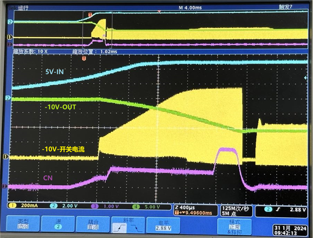
The circuit is typical ckt in datasheet. It generate +/-12V output from +5V input. The load current is +/-20mA (MAX). Most of time the circuit working properly, but with a very low opportunity the negative output is always 0V, at the same time the possitive output is allways correct +12V. They observed the negative inductor current waveform during start up with questioned circuit. It shows the circuit trying to start up negative output however after a while the negative DC/DC stopped switching. The inductor current reach to arround 1A peak before it stopped. It cannot try again once stopped. It is confirmed it is not due to UVLO or thermal protection since the possitive output is always correct. And the device is not damaged since it can resume work some other time or change another inductor. I cannot find any other protection feature can result such kind of phenominen.

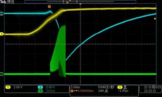
 Attached is the start up waveform with: possitive o

utput, negative output , and inductor (negative) current.

Thank you,

John

  • Hi John,

    How many devices have been found this issue and have customer tried ABA test?

    BR

    Patrick

  • Hi Patrick,

    thankyou for quick response. 
    the device is not failed. It can resume work through replacing inductor (with higher inductance value, but the old value is following the datasheet recommendation). I don’t think it make sense to do ABA test, which is used to check if the device failed. 
    regards

    John

  • Hi John,

    Could you please share the schematic for me to double check first? You could send it to me with private message if customer has confidential concern.

    BR

    Patrick

  • here it is:

  • Hi John,

    Will remove C148 and R185 provide any help?

    BR

    Patrick

  • Hi Patrick,

    Is there any possible connection between this RC network and the start up issue? TPS65130EVM also use similar RC network but with different capacitance, (EVM use 12pF/10k, customer design is 68pF/10k)  My understanding is this RC network is for loop compensation, improper RC value may result stability problem. While the issue is not a stability problem. (Most of device can start up properly, and once start up the loop is stable.)

    Regards,

    John

  • Hi John,

    Because when internal FET stops switching, then the negative voltage will drop to 0. So I suspect that the control loop wrongly turned off the FET, and this feedforward capacitor might have impact to control loop. Not only stability concern.

    BTW, the feedforward capacitor is recommended to follow equation (12) in our datasheet. 

    BR

    Patrick

  • Hi Patrick,

    Ok I can have customer do the test you required though I do not think so. I do not think the incorrect feedforward capacitor can make the control loop continuously turn off the internal FET. There should be some protection features that keep the FET turning off.

    Regards,

    John

  • Hi John,

    BTW, how many ICs have found this issue?

    BR

    Patrick

  • Hi Patrick,

     The ‘failure’ rate is very low, no detailed data. This is a GI customer who think much about the reliability. So they want to find out the root cause, in stead of just close the problem.

     Thank you!

  • Hi John,

    OK, definitely we should find the root cause.

    Could you please kindly ask customer to capture the voltage waveform on CN pin when power on the device and when this issue occurred? This will provide more evidence if the EA output goes wrong.

    BR

    Patrick

  • Hi Patrick,

    Ok. Another information customer supplemented is: the start up problem is not occured every time when power up the questioned device. The problem only occured roughly once every 10 times of power cycling on questioned device. And once start up, every thing is correct. 

    Regards,

    John

  • Hi John,

    Noted, and what if the 20mA load on negative rail is removed, will this issue still be reproduced?

    BR

    Patrick

  • Hi Patrick,

    This test is not easy to do on customer's board. But I do not think it make sense to do such test, 20mA is far below the capacity of this device. 

    I think there are should be some kind of hidden protection feature (other than UVLO and thermal protection) that lock-off the negative convertor, possibly overload protection. 

    As the datasheet says, in 'Soft-start' section, the device allows 1ms of soft-start time to ramp up switching current limit. However it does not explain what will happen if the output voltage cannot achieve regulation during soft-start phase. I am guessing the device's response is lock off if the soft-start phase expires while output voltage cannot reaching regulation. From start up waveform you can also find, after 2ms of soft-start, the switching current has ramp up to about 900mA (maximum limitation of the device) while the voltage is still not regulated.

    So could you please help me confirm if this device has such kind of hidden, lock off, overload protection feature?

    Thank you!

    John

  • Hi Patrick,

    I scrolled back through similar posts about TPS65130 found there a lot of posts reported similar problem. While none of them give final solution.

    One of possible cause frequently mentioned in those posts is noise coupling through feed forward cap, this may result VOUT cannot be regulated. However I this cannot match my case. In my case VOUT is 0V, instead of some other lower voltage. And inductor current was observed completely dropped to zero. So no noise coupling at all.

    Thank you!

    John

  • Hi John,

    Based on datasheet, seems no additional protections.

    Could you please send me the CN voltage waveform then I can search some help from our design team? Thanks.

    BR

    Patrick

  • Hi Patrick,

    Unfortunately they cannot find out the old questioned board. They cannot replay the same issue with current board. I have engineer tested the start up waveform with correct board, see attached. 

    Comparing the two waveform you can find, both board have about same soft start time, 2ms, the only difference is the questioned board cannot ramping VOUT to target voltage, while correct board ramping up the VOUT to target voltage.  If this is the root cause that lock off the device?

    Thank you!

    John

    .

  • Hi John,

    From my side, the negative output voltage ramp down to 0V is more likely the result, not the cause. To find the root cause, firstly the issue board CN voltage waveform is still needed. 

    BR

    Patrick