This thread has been locked.

If you have a related question, please click the "Ask a related question" button in the top right corner. The newly created question will be automatically linked to this question.

LM5176: High Input current with no Load

Part Number: LM5176
Other Parts Discussed in Thread: LM5175, LM5175EVM-HD

Hello,

I have copied more or less the EVM. It works quite well, but it loads 110-120mA from a 7-8V input while is no load on its output. The circuit output is set to 12V so it works in Boost mode.

The used coil on first trial XGL1712-153, later changed to XGL1712-472, but nothing changed on load current.

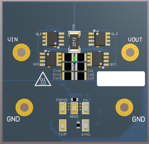
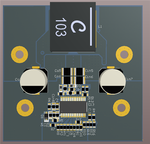
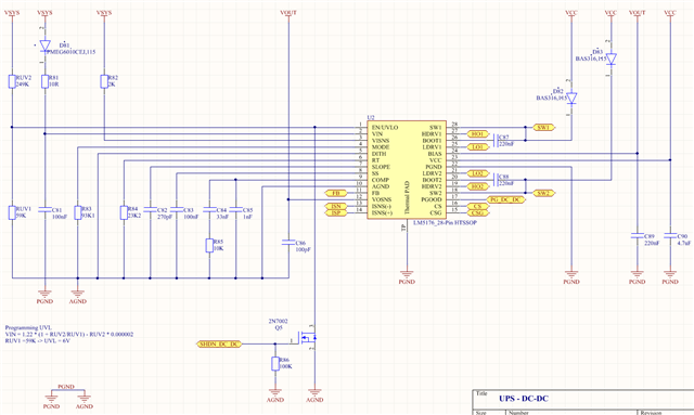
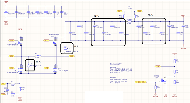
Attached the schematic of LM5176, and the power part.

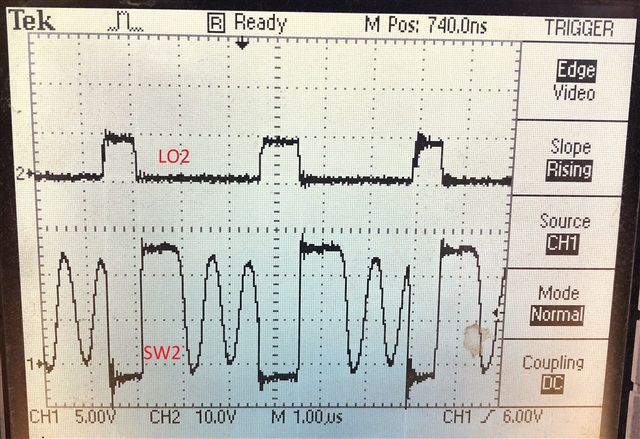
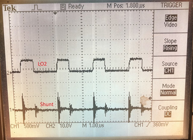
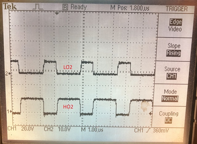
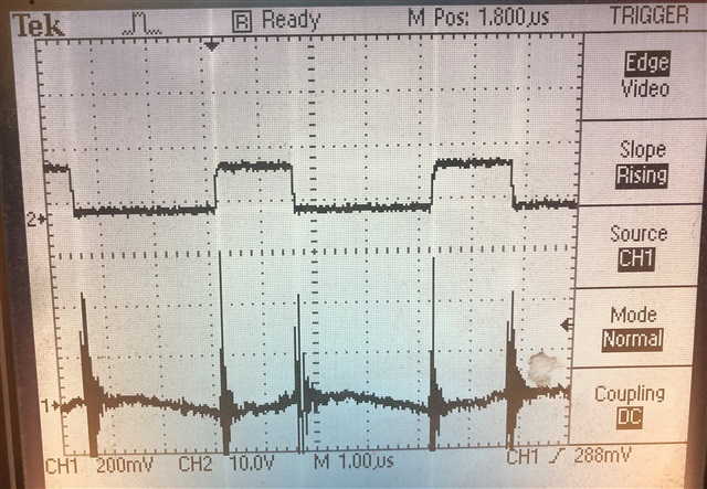
Attached oscilloscope picture of the shunt and LO2 gate, also LO2 and HO2 gate too.

The circled parts are not populated for now, but later would be added to reduce ripples.

Any idea is welcome.

Thank You in advance !

Zoltan

  • The 2 diodes from VCC are going to BOOT1,2, there is a misstake on schematic, but corrected on PCB. Still same high current without load.

  • Hi Zoltan,

    Thank you for using E2E threads, please allow us some time to get back to you.

    BR,

    Haroon

  • Hi Zoltan,

    as the device is still operating and switching there is some current required to switch the MOSFETs.

    This depends on the Gate Capacitance of the MOSFET and the switching frequency.

    The LM5176 works in FPWM mode only. Using the LM5175 with DCM mode can help to reduce the power consumption at no load.

    Note: the device is pin compatible but requires a different RT resistor

    Best regards,

     Stefan

  • Thank You Stefan !

    I will try the LM5175 too. Till will receive them Im thinking to reduce the switching frequency, hoping to reduce some of the load current.

    The EVAL kit description says "Set the power supply voltage to 9V and the load to 0.1 A. The electronic load voltage must be in
    regulation with a nominal 12 V output." Unfortunately the input current is not mentioned. Im wondering if the EVAL kit loads also same high current as mine ? - as Im using same Fets.

    All the best !

    Zoltan

  • Changed RT to 33K, frequency changed, but the spikes on the shunt remains same.  Input current dropped to 90mA, still more than expected.

  • Hi Zoltan,

    Losses in SMPS are mainly defined by:

    - Loss by RDS,on of the MOSFET

    - inductor loss

    - switching loss of the MOSFET (Gate Charge)

    - Loss in Controller

    Each switching of the MOSFETs consumes some power, so even if there is not power transferred the switching losses are there.

    When measuring the voltage on the Shunt the setup needs to be done very carefully to avoid noise pickup and disturbance injection into to the probe.

    Esp. with Ground connection of the probe and injection loop can be build easily. To avoid this the so called tip and barrel method for measuring is recommended.

    See: 

    Common Mistakes in DC/DC Converters and How to Fix ...

    -> shows Tip&Barrell - page 28

    Best regards,

     Stefan

  • Hello Stefan,

    Changed to LM5175, but this circuit makes me crazy. It still had a load of 100mA without load. And I see strange signal on SW2.

    Changed the coil too, to XAL1510-472MED but same signal:


    Loaded the 12V output a little with 2A, while it runs from 6V input. It played a nice music, but thats clear due to the less capacitors. After removed the load all turned back to "normal", while the the consumption remains at 180mA.

    It looks than even I try to decrease the power consumption that is increasing, with my each intervention.

  • Finally downloaded the  LM5175EVM-HD design files. Modified the PCB from 6 layers to 4 and changed the mosfets, shunt and coil footprint. Released in production some samples. Lets see, will update results once will receive.

  • Hi Zoltan,

    the waveform you see on SW2 above is a typical DCM waveform when inductor current goes down to 0A.

    Please let me know once you receive the updated PCBs.

    Best regards,

     Stefan