This thread has been locked.

If you have a related question, please click the "Ask a related question" button in the top right corner. The newly created question will be automatically linked to this question.

BQ25672: Schematics review

Part Number: BQ25672

Hi,

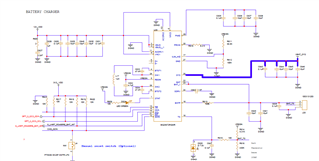
I am designing a custom board with BQ25672.

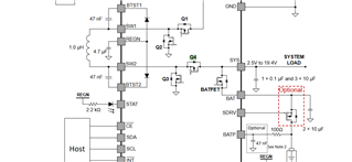
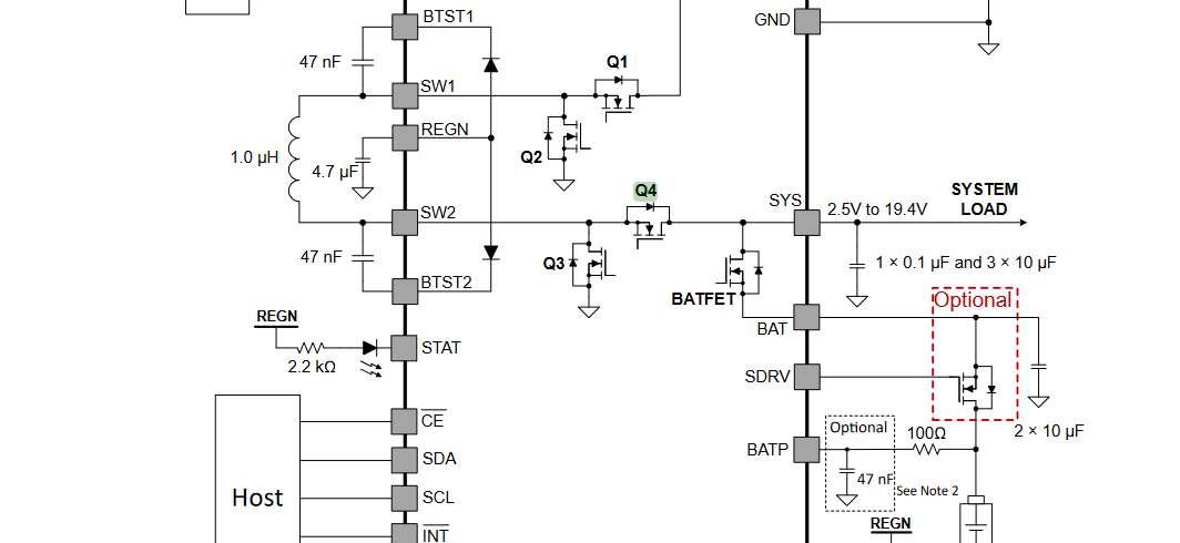
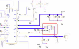
Can anyone review my schematics and provide valuable comments. Also, I have few questoion:

  1. our power supply specification is 12V, 2.5A. System load is 10W and we are using 2s,2P battery with 6.7Ah rating. Is input 2.5A is sufficient for our application considering battery charge current of 1A?
  2. What is the switchover time when VBUS input is gone and battery voltage comes into play to provide sys power?
  3. Current rating of BATFET?

Amit

  • HI Amit,

    I don't see any obvious issues with the schematic.

    Regarding 1, using efficiency power balance:  eff=BATREG*(ICHG+ISYS)/(VBUS*IBUS) -> ~0.93 = 8.4V*(ICHG+10W/8.4V)/(12V*2.5A) gives ICHG=2.13A.  So assuming constant 10W load, the battery charges in 6.7Ah/2.13A*1.3 (0.3 to account for tapering) ~ = 4.1hours.

    Regarding 2, SYS is always connected to BAT by a diode.  The internal FET turns on in microseconds.

    Regarding 3, 

    Regards,

    Jeff

  • Hi Jeff,

    Thanks for the quick reply. Few more queries.

    1) My battery discharge cutoff voltage is 6.4V when discharging. Where I can set this to prevent battery discharge beyond 6.4V?

    2) what will be the VBAT_LOWV for 2s2P battery which I am using and can I set this parameter?

    3) What is the current rating of Q4 when system is powered by input source?

    4) is there a way I can turn off BATFET from host to meet my serial no 1 requirement?

    Amit

  • Hi Amit,

    Regarding 1, the VBAT_UVLO is fixed at the values below.

    The battery pack protector IC has a discharge FET that can be set to prevent discharge below 6.4V. 

    Regarding 2, VBAT_LOWV is the voltage at which the charger transitions from pre charge to fast charge.  It is set as a % of BATREG in I2C REG0x08[7:6].

    Regarding 3, the max output current from the converter is 5A.

    Regarding 4, no.  The internal BATFET has body diode that is always present.  Also, there is no bit for the host to turn off the external shipFET as long as input power is applied at VBUS.

    Regards,

    Jeff

  • Hi Jeff,

    Thanks for the reply.

    Again coming back to my question 1, if I use an external FET between  BAT and SRDV pin, I can monitor my  battery voltage by reading VBAT_ADC register and when it reaches my low level i.e. 6.4V , I can enable shutdown mode using SDRV_CTRL[1:0]. Whether this approach will work?

    Updated schematics of mine:

    Amit

  • Hi Amit,

    Unfortunately, no.  SDRV can only be turned off for ship mode or shutdown mode, which can only be entered if VBUS does not have a valid voltage, i.e. no adatpor present.

    Regards,

    Jeff

  • Hi Jeff,

    Yes my question was in case of adaptor is not present and battery is in discharge mode and when battery voltage reaches 6.4V I can turn off SHIPFET right.

    I dont want to do this when adaptor is present.

    Amit

  • Hi Amit,

    Then yes, that will work. But I still recommend a pack protector IC.

    Regards,
    Jeff

  • Hi Jeff,

    My pack has the protection till 5.6V but i want to have this 6.4 v from host side.

    Amit