Hi TI Team.
I am designing a board where I use the TPS61023 boost converter. Input = 3-4.2 V. Output = 5V at 1A.
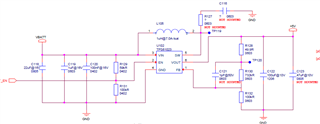
The connections are the following:
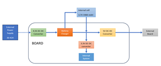
As you can see, 5V DC-DC Converter (TPS61023) can be powered from the internal cell or from an external power source.
When the internal cell is connected, 5V DC-DC converter is working fine with no load and with load, but when the TPS61023 is only powered from the external source and I applied a load, there is a drop voltage and 5V Vout starts ringing (affecting the other voltage rails). (I am supposing it is ringing, not a loop instability).
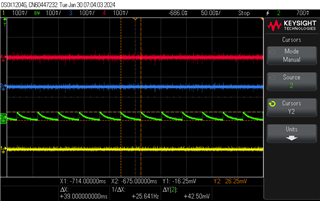
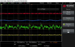
Please see images below with ripple voltage of 4.55V DC-DC converter Output (RED line), Internal cell/Battery Charger Output (VBAT-BLUE line), 5V DC-DC converter Output (GREEN line) & 3.3V DC-DC converter Output (Yellow line).
1. 5V DC-DC converter with no load. Internal cell connected.
Ripple is OK, 42.5 mV.
2. 5V DC-DC converter with load (0.5 A). Internal cell connected.
Ripple is OK, 5.75 mV. Frequency is OK, 1.03 MHz.
3. 5V DC-DC converter with no load. Internal cell disconnected. External power source connected.
Similar graphic as in point 1.
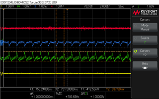
4. 5V DC-DC converter with load (0.5 A). Internal cell disconnected. External power source connected.
Ripple is really high, around 1.05 V and frequency is NOT OK, 793.65 Hz. 5V is not well regulated.
I use TI Webench as reference for the design, below is the SCH and the Layout, so you can check it.
For the graphics showed above, I soldered the feedback capacitor C121 and the output capacitor C123.
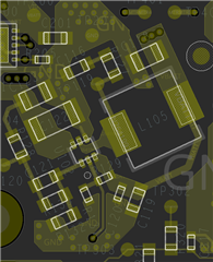
Layout is the following:
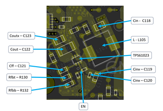
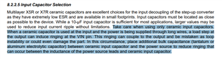
Checking EVM and datasheet is recommended increase input capacitance with a tantalum capacitor, I soldered T55B107M6R3C0035 at the input of 5V converter. Also, I increased the output capacitance of same converter with the same tantalum capacitor.
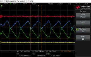
The response adding 100 uF at input and output of the 5V converter is the following:
5V DC-DC converter with load (0.5 A). Internal cell disconnected. External power source connected.
Ripple is now 200 mV, and frequency is 3.448 kHz. Still the regulation is NOT OK but it's not as bad as without the tantalum capacitors, so, I am thinking in increase the input capacitance.
Please check the SCH, layout and graphics and let me know your comments to solve this issue.
Thanks in advance.